“EMG-6 Shop Notes” is a day-to-day accounting of what’s going on in the shop with the EMG-6 Electric Motor Glider.
March 24, 2017
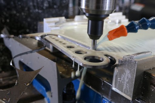
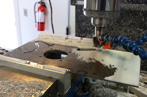
The elevator control horn being machined from .125 4130 steel plate.
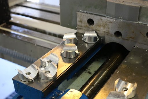
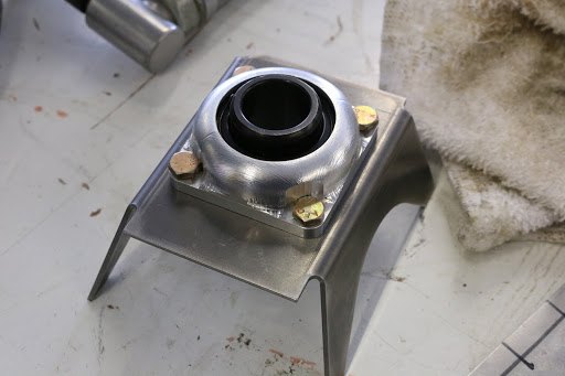
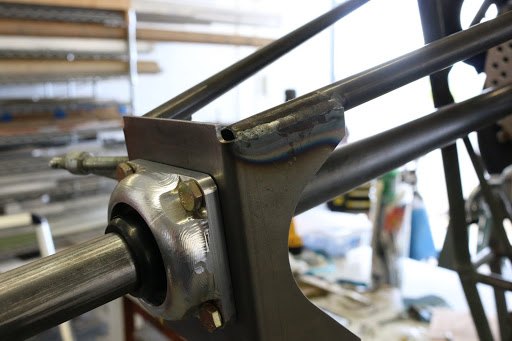
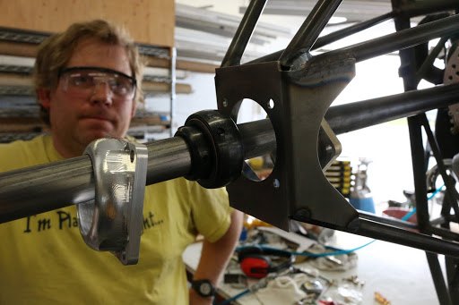
The control stick bearing saddles after manufacturing. The saddles capture the control stick and provide additional support at the bearing surface.
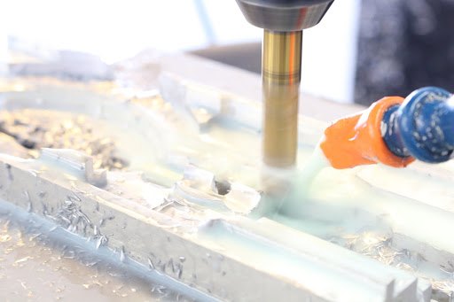
The saddle being cut out of one of the fittings.
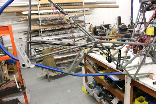
The rudder pedals with the control arm attached, pushrod tubes installed, and attachment to the idler arm at the passenger rudder pedal location.
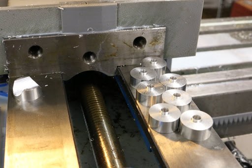
The saddles are manufactured from 6061 T6 aluminum. The first step is to cut blanks to the exact diameter and thickness in the CNC lathe. Then we move the fittings to the milling machine for cutting the saddle.
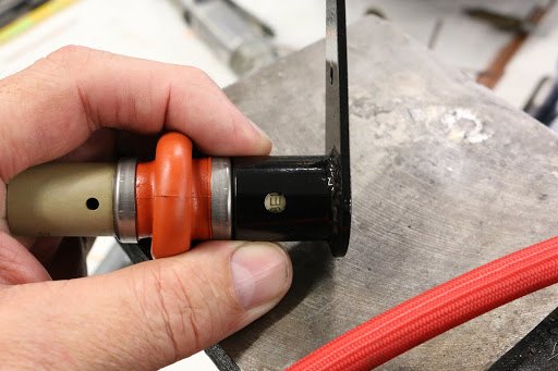
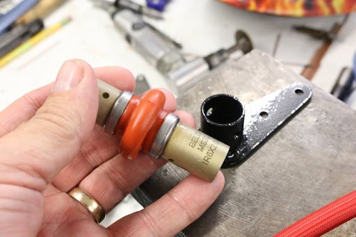
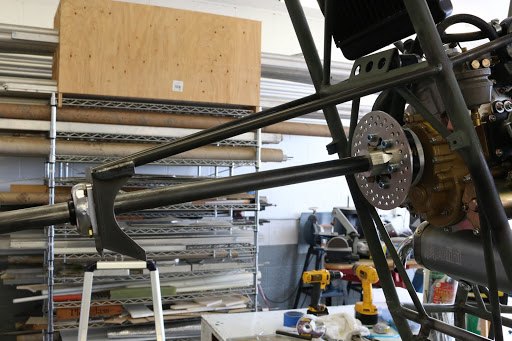
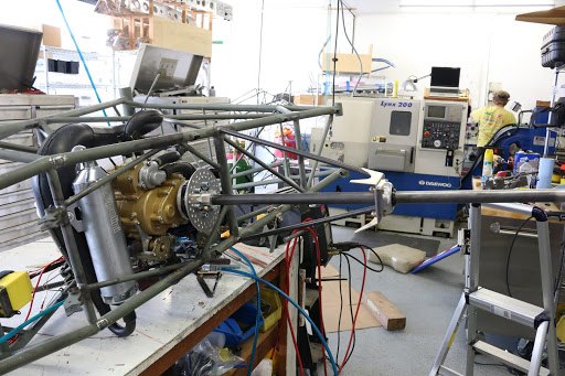
The U-joint interface to the control stick which runs the aileron torque tube to the aft section of the fuselage frame.
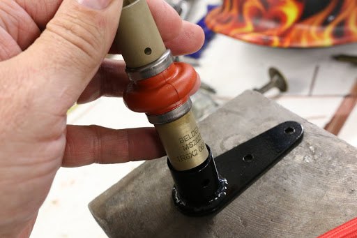
We are using an MS U-joint. These fittings although expensive are very reliable, have a high torque load capability, and a silicone boot that keeps them lubricated indefinitely.
March 22, 2017
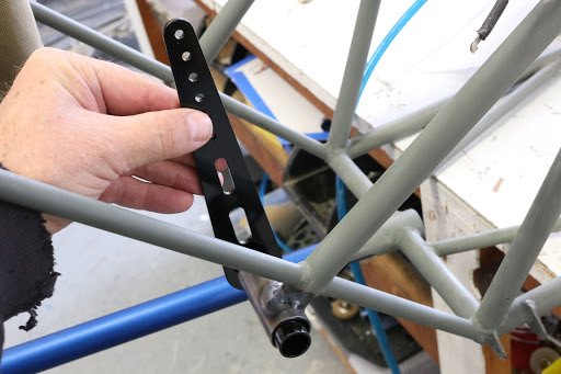
The passenger rudder pedal/idler arm in position.
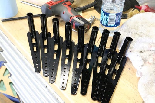
We have enough orders currently that we are having to make multiple components. These are series of the passenger rudder pedal interface/idler arm.
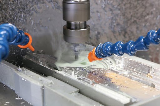
Machining out the rudder control arm.
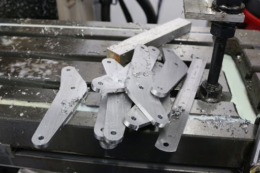
The machined rudder control arms. These will be bolted to the rudder pedals to provide a control pushrod attached location as well as a foot guard to prevent your foot from interfering with the fuselage structure.
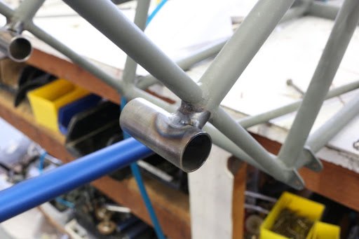
The passenger rudder pedal/idler arm bearing support being tack welded in place.
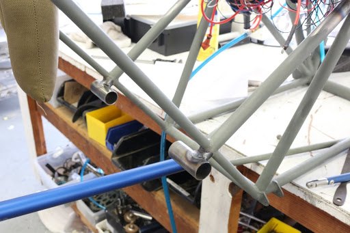
The bearing tube for the idler arm, identical on each side.
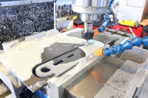
The idler arm being machined from .125 4130 chromoly steel plate.
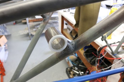
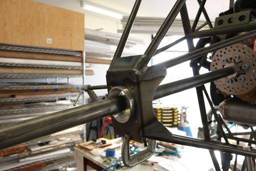
The flight control stick bearing mounts with the nylon bearing inserted.
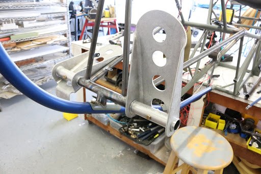
Rudder pedals installed with the new rudder pedal bushings. The center tube is used as a spacer and locator for the rudder pedals.
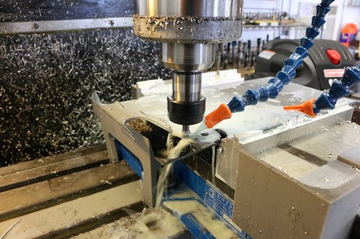
Machining the control stick bearing plates.
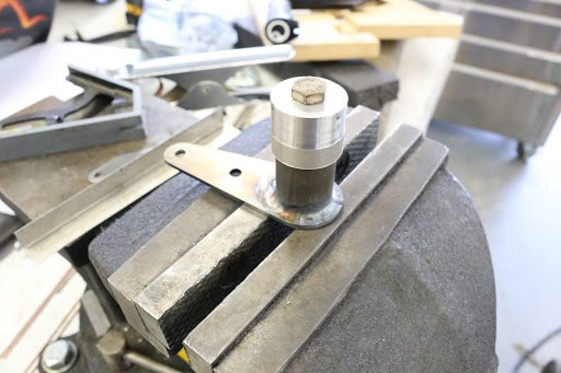
One of the bearing plates is used as the U-joint attach fitting. In this picture here we see the U-joint attach fitting after being welded. The aluminum block on top is an alignment fixture to ensure accurate positioning during the welding process.
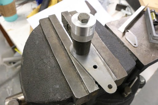
The same U-joint fitting prior to welding.
March 21, 2017
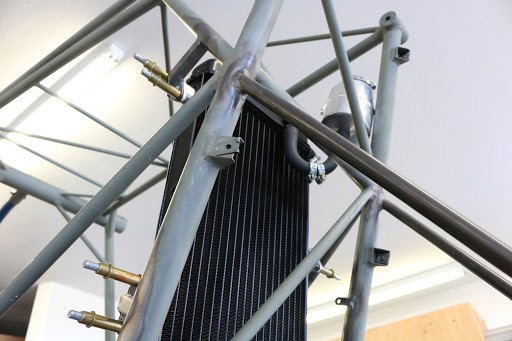
We have developed a very clean installation for the radiator. Once installed can be removed with simply two bolts.
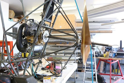
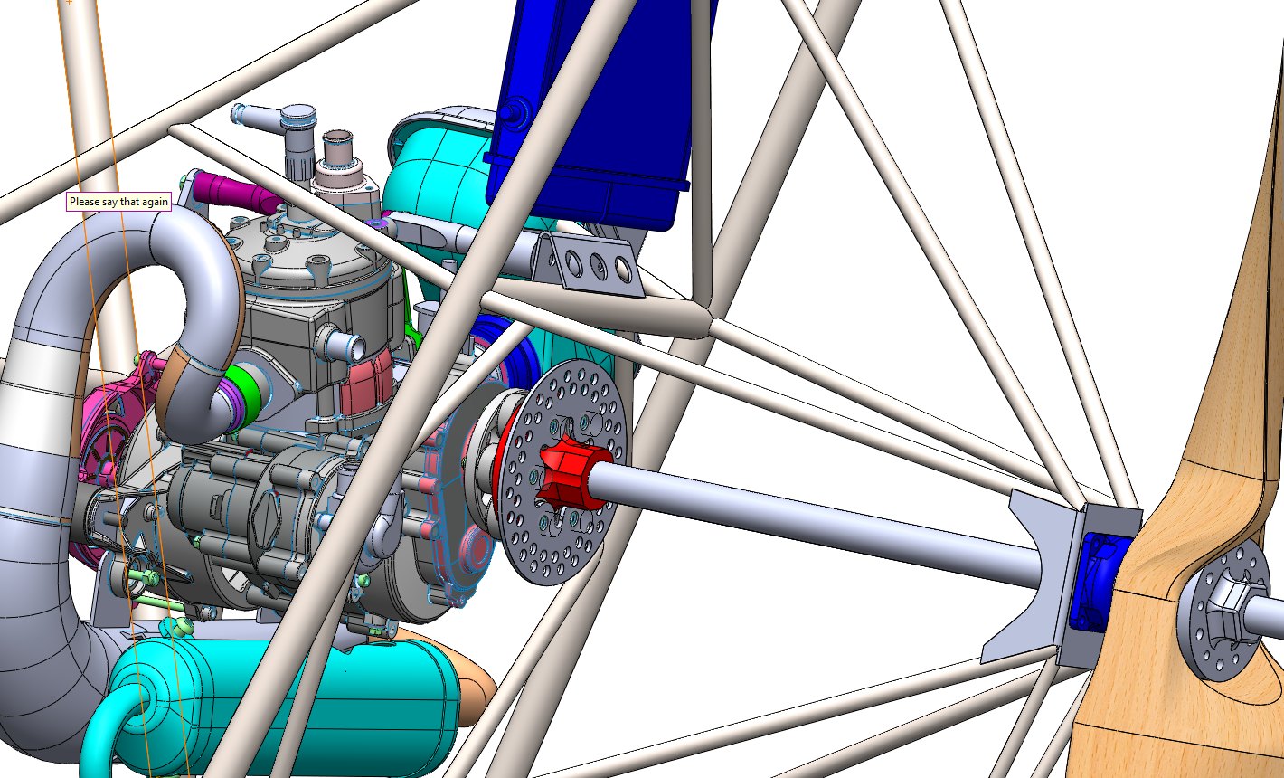
The drive system coming together showing the interface of the propeller and driveshaft.
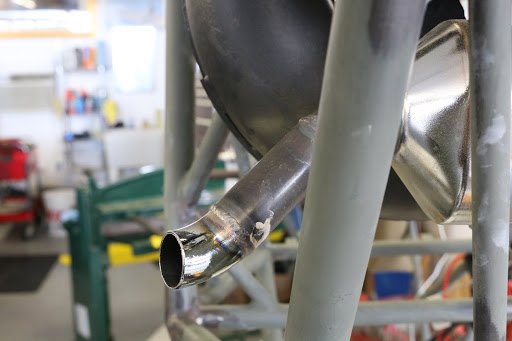
We made a slight extension to the exhaust system to allow the exhaust to exit a little further away from the fuselage fabric.
March 20, 2017
With the prop shaft idler bearing now complete, we have installed the propeller with the prop shaft mount and the crush plate located on the forward side of the propeller.
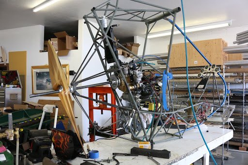
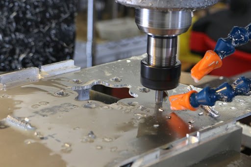
Manufacturing a smaller replacement support for the driveshaft coupling mount. On the prototype we will be testing the driveshaft coupling system without the propeller brake.
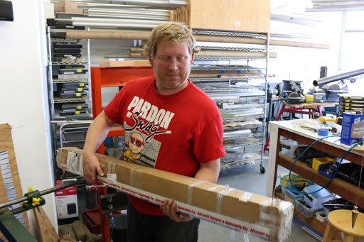
Surprising, but this box from aircraft Spruce contains all of the 4130 steel tubes necessary to build the fuselage frame. Because most of the tubes can be nested inside of each other, they can be condensed into the small package. From the very beginning the fuselage frame was designed with the longest tube to be no longer than 48 inches. This keeps the UPS shipping to a minimum for a fuselage frame kit.
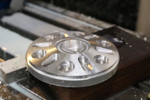
One half of the propeller crush plate machined.
March 18, 2017
We are continuing to work on the details of the Polini 250 engine installation as well as the mounting of the accessories. We also beginning work on the flight control systems.
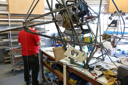
The aft idler bearing with the remaining support tubes installed.
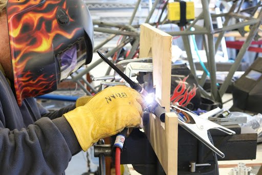
In this picture here we are tack welding welding the control stick.
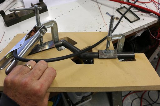
The welding fixture manufactured from MDF (medium density fiberboard) ensures that each control stick is manufactured and welded to the exact tolerances.
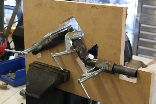
The welding fixture has cut outs to allow for welding the control stick and installation of mounting clamps to hold the tubes in place during the welding process.
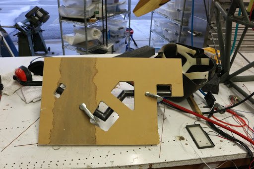
If the fixture is flipped over you can still access the rear side of the weld joints.
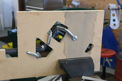
Another view of the control stick partially tack welded while still in the fixture.
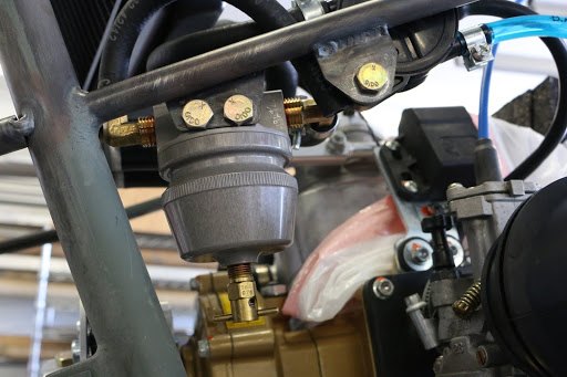
We have removed the fuel gas collator from its original position and positioned it closer to the carburetor. This will be easier to access through the access panel on the right side of the fuselage frame.
March 17, 2017
We are continuing work on the Polini 250 installation.
Cutting out of the prop shaft idler bearing support plate.
After bending the support plate and mounting the idler bearing for the prop shaft
The initial positioning and installation of the idler bearing
A close-up of the idler bearing housing mounted to the plate.
Even with the engine mounted in the aircraft the whole assembly is so light that we can rotate it and position it for welding fairly easily.
With the idler bearing disassembled, you can see how the idler bearing housing captures the idler bearing between the sheet-metal mounting plate.
With the bearing removed, the forward bearing mount is shown how it is captured between the 4130 steel mounting plate. Even with a complete bearing failure the prop shaft should remain contained within the housing.
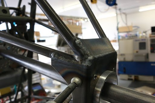
A close-up view of the welded flange.
March 15, 2017
Polini 250 installation continues.
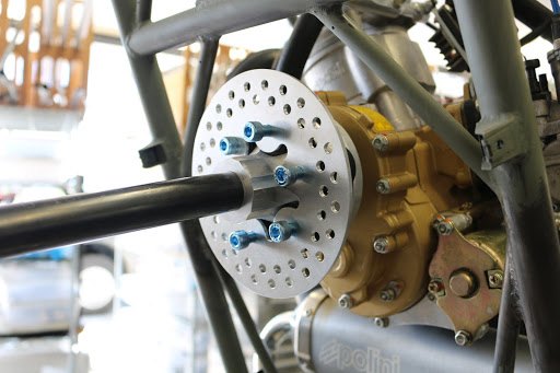
The drive coupling and the propeller shaft brake being installed.
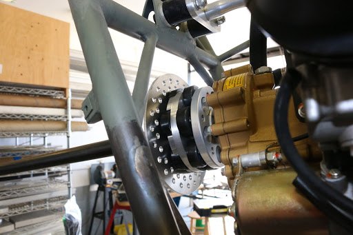
A view from the engine side
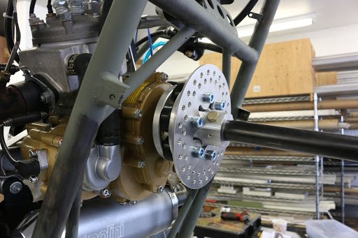
With everything tightened up, and the prop shaft installed.
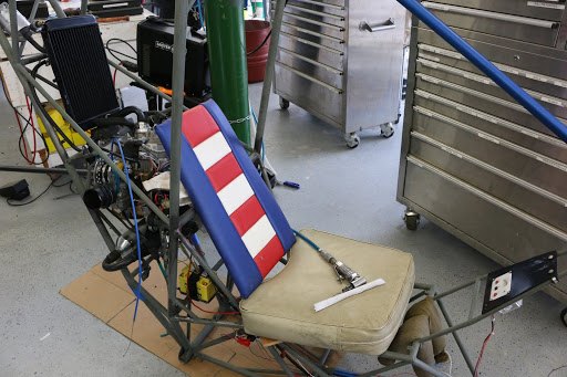
Before installing the rudder pedal mounting tube, we set up dummy seat and seat back to just verify rudder pedal positioning.
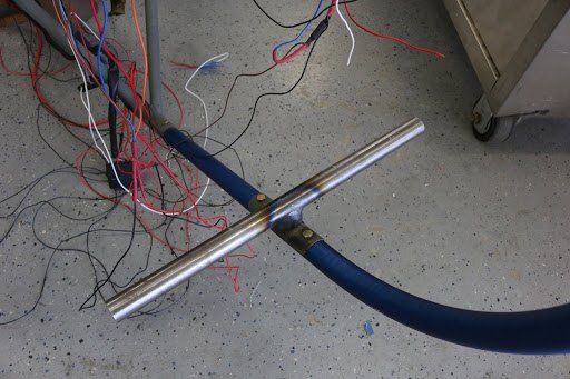
Once we’ve established the proper position for the rudder pedal mounting tube, we clamp it in position, check it with a bubble level, and drilled the 3/16 inch diameter bolts through the keel assembly.
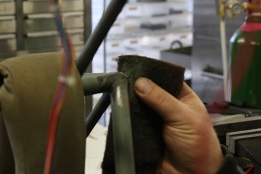
The next tube to be installed is the support tubes from the forward pilot seat to the rudder pedal cross tube.
After those tubes have been installed, the next tubes are the tubes from the instrument panel keel pocket down to the rudder pedal cross tube.
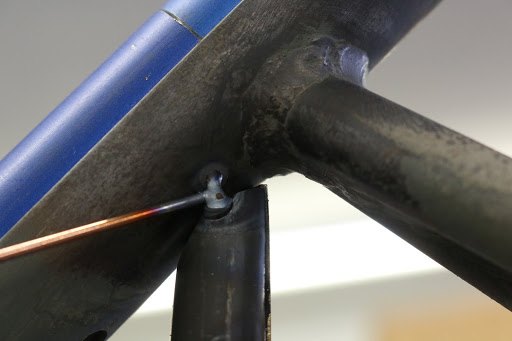
Because the aluminum keel tube is installed during this process and absolutely minimal tack weld will be used to hold the tube in position until the keel can be removed.
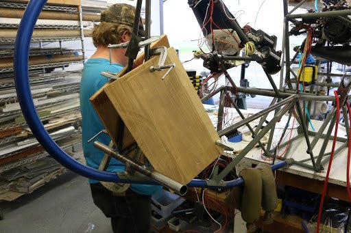
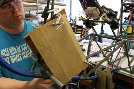
The two tubes that mount to the rudder pedal cross tube are on the same plane, and so using a board to ensure alignment during the tachometer welding process makes it easy.
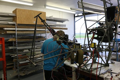
Once the keel has been removed from the forty-one thirty steel frame we can continue the rest of the welding on those joints in the vicinity of the keel tube.
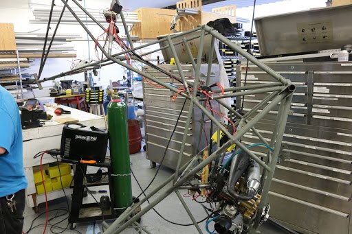
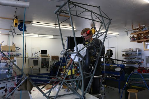
One of the big advantages of working with the frame without the fuselage boom attached, is that it is easily positionable for any welding that is necessary. In the future were going to recommend that the entire fuselage frame with all the controls be completed before we ever attach the fuselage boom. It’s just so much easier.
March 14, 2017
Flight control systems being installed.
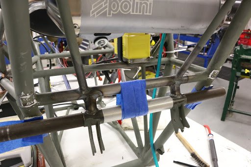
We have started the installation of all of the flight control systems, in this picture here we have tack welded the primary support tubes that attach the rudder cable pulleys and these also act as the pivot shaft for both the elevator and aileron control system.
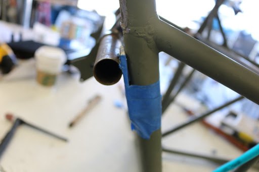
By pre-manufacturing the supports, we can use a through tube with a very specific dimension from the rear bulkhead to provide proper positioning.
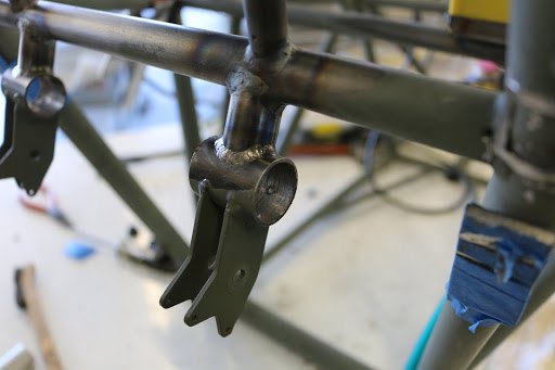
Once the tubes have been tacked. The rest of the welds can be completed around the rudder cable pulley standoffs.
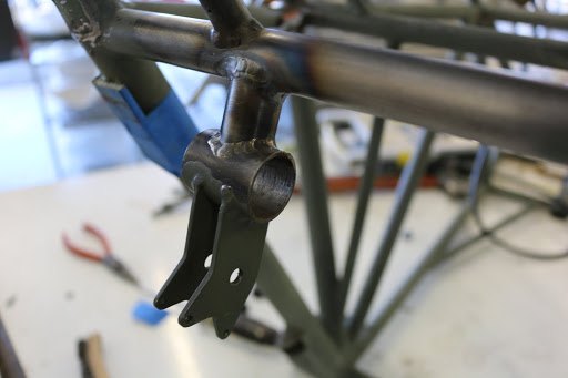
One for the left side and one for the right side rudder pedal pulley support.
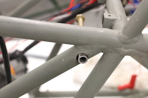
Positioning of the pilots seatbelt attach bushing.
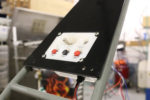
The Polini 250 control box temporarily positioned on the instrument panel bulkhead. This will interface and be positioned in conjunction with several other items that are located on the instrument panel.
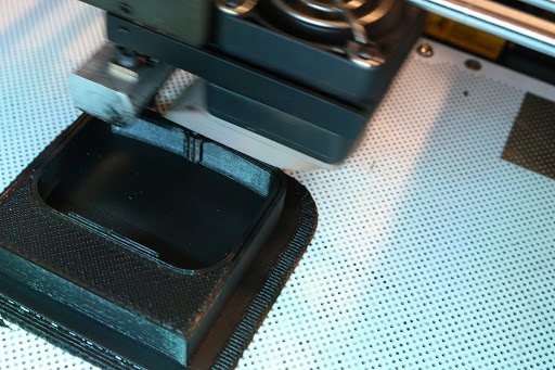
One of the things that we will be installing onto the instrument panel is the icon radio holder. In this picture here you see the 3D printer beginning the process of making the ICOM radio mount.
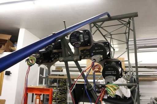
In conjunction with all of the other subsystems that are being mounted onto the airplane we have started to wire up the instrument panel.
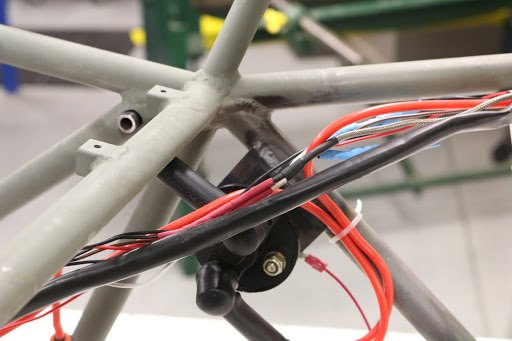
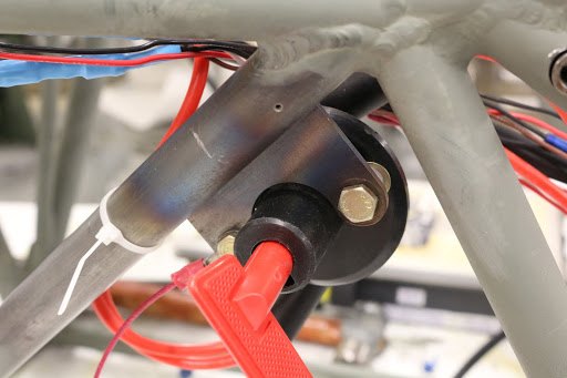
In order to save weight we have installed a manually operated master switch.
March 13, 2017
We are nearing completion of the new drive coupling system to be utilized on the Polini 250 installation. In order to reduce the drag, mounting of the propeller further aft is required.
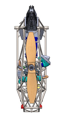
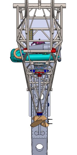
A bottom view and and aft view shows a significant improvement in the profile.
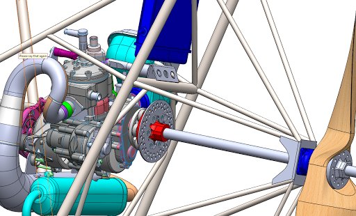
The basic configuration look something like the picture above.
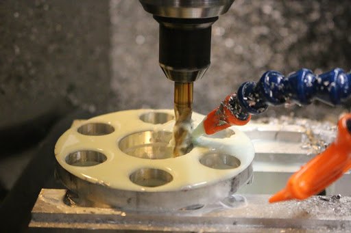
Machining the interface hub.
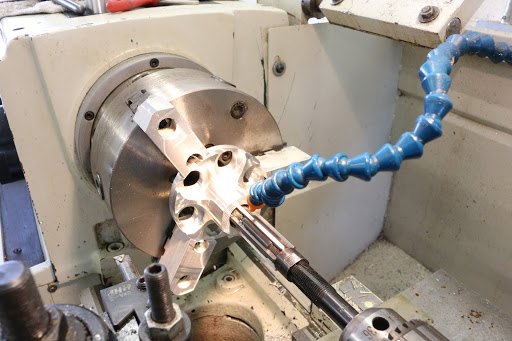
In this process here we are reaming the interface hub to a very precise fit on the prop shaft.
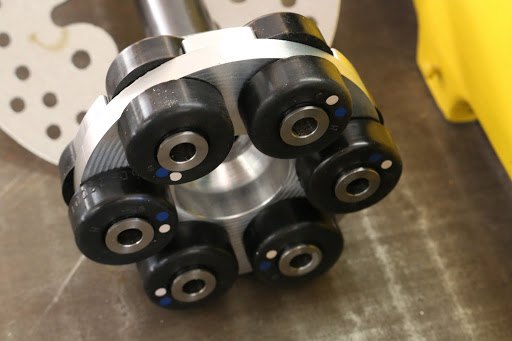
The completed driveshaft coupling subassembly. The vibration damping amounts are available in a multitude of different durometer’s. Because the mounts will be mounted directly to the aluminum engine hub, we had the manufacturer special stainless steel bushings to insert into the rubber mounts that will provide for a large surface area against the aluminum hub.
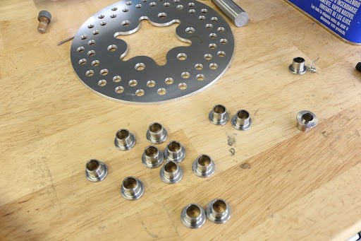
A collection of the stainless steel bushings that will be used to interface with the vibration isolator mounts directly to the engine prop flange as well as the prop brake.
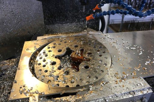
In this picture here we see the propeller brake just after machining. The propeller brake is something that we wanted to experiment with as a result of the original tests on the airplane with the Polini 250. Because the Polini 250 has a centrifugal clutch when the idle on the engine is brought back below 3000 RPM the centrifugal clutch disengages and the propeller can now free will. If you’ve ever flown a multiengine aircraft with one engine shut down you know the importance of being able to feather the propeller or at least stop it to reduce the horrendous amount of drag created by the propeller spinning in the wind basically operating as an auto Gyro. Although the drag from the freewheeling propeller was not unacceptable. The ability to use the aircraft as a glider can be significantly improved if we can stop the propeller in-flight.
March 12, 2017
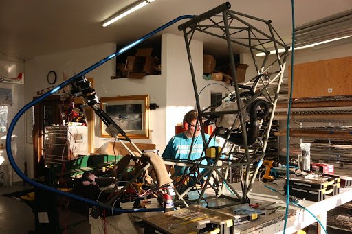
We have mounted the instrument panel and are now in the process of completing the wiring for all of the subsystems.
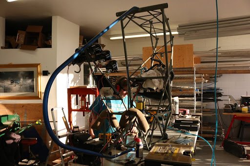
We have mounted the keel subassembly so that we can now position the rudder pedal support tubes.
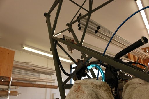
The fuel system from the gas collator to the fuel pump and onto the carburetor has now been installed.
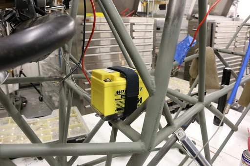
We have installed the battery box and battery.
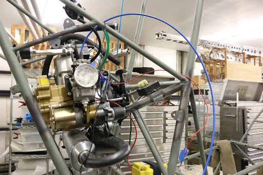
The tabs sticking out our for mounting the starter relay.
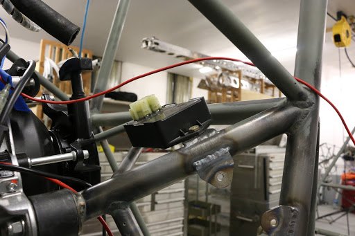
The installation of the secondary ignition module.
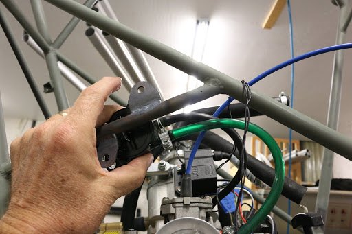
And positioning the fuel pump close to the carburetor to reduce the pulse line length as well as the most direct routing to the carburetor.
March 11, 2017
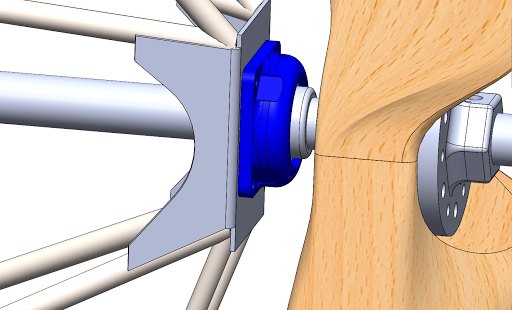
We’ve had to redesign the housing for the bearing assembly. We purchased a flannel mounted bearing that is rated for what we need, however, the weight of the original bearing housing manufactured from cast-iron was just outrageous.
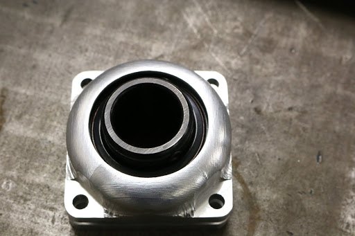
We designed a two-part bearing housing manufactured from 6061 T6 aluminum which will keep the trailing edge profile to the absolute minimum.
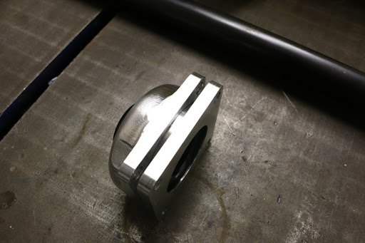
The bearing housing will capture the rear fuselage 4130 chromoly steel mounting plate in between the 2 bearing holders.
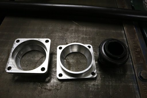
The housing is manufactured with an interior ball socket so that the bearing can be placed in position and then clamped together allowing for up to about 10° of misalignment.
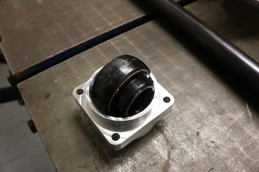
You can see in this picture that the housing will fit the bearing even at 90°.
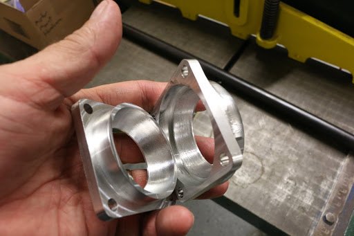
The 2 halves of the housing interface with each other to provide a large surface area for the bearing to ride.
March 10, 2017 Back In the Shop
You may have noticed that we been out of the office now for almost 3 weeks. We were visiting Asia and specifically Hong Kong, Taiwan, Japan, Korea, and several other Chinese cities. We normally work 10 to 12 hour days 7 days a week and the compromise that I agreed to is, that Carol gets to choose a vacation of her choice anywhere in the world. Fortunately we only have to do this every 18 months.