Hangar · August 2015
Manufacturing 9" Radius Tube Bending Dies
Brian Carpenter · Rainbow Aviation
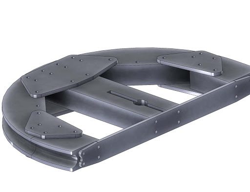
Bending Die Design
Main Bending Dies Segment
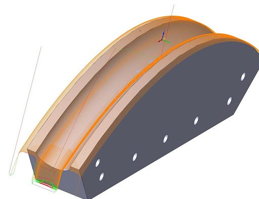
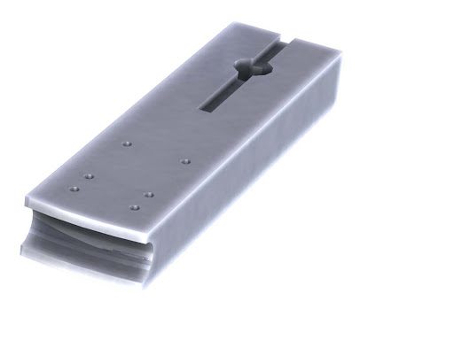
In order to facilitate simple construction. We next manufactured to identical bending segments that will fit on either side of the Keystone which will do the majority of the bending.
We 1st design. The part in Solid Works and then lay out the tool-path in Solid Cam. In this picture here we see the finish toolpath represented an orange stepping over every .010 of an inch. Creating a smooth contour.
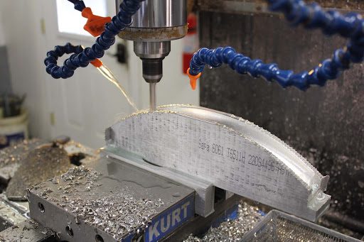
In this picture here we can see the milling machine working the finish path on the 1st segment. This will also require re-positioning the component for the additional machining after this Tool-path has been completed.
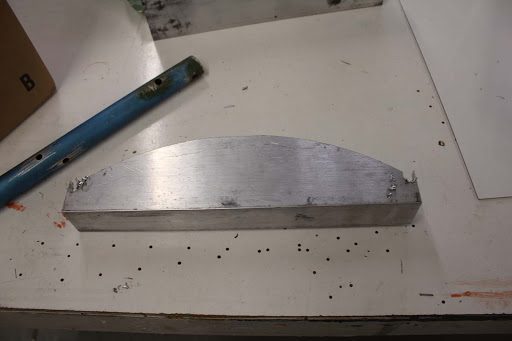
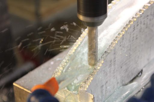
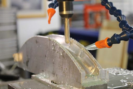
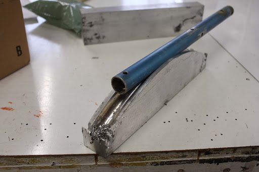
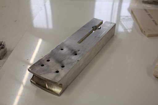
A sample piece of tube is been placed next to the radius of the bending dies. We will keep the radius about .008″ Smaller than the tube to assist in maintaining tube concentricity during the bending process.
August 21, 2015
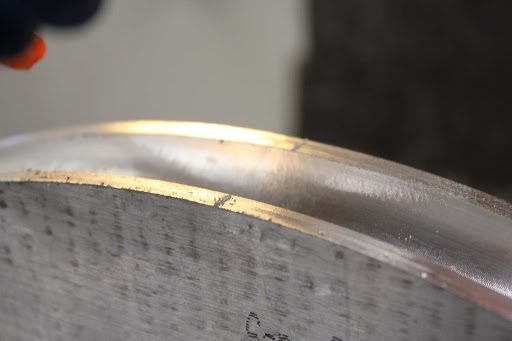
Once the basic profile of the bending block has been machined we also machine in index marks which will be used for the re-positioning of the part in its new orientation.
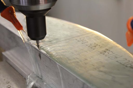
In this picture here we see the bending block re-positioned onto its side and an additional reference mark made down the center of the bending block which can be used later for additional references.
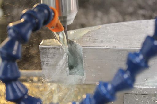
The side profile is then cut to the exact dimension for interfacing with the key block and the other end segments
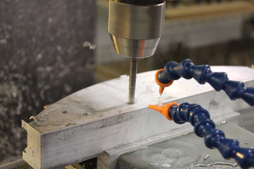
.
Next the holes will be drilled into the block which will be used to tied together all of the individual components with the interfacing plates.
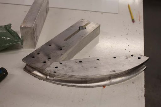
The primary segment shown as it fits with the key block.
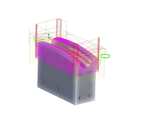
The end to final segments are required to make up the complete assembly. These will be used to tie both ends to the the key block. In this picture here we see the tool-path for both the rough cutting and the finished cut.
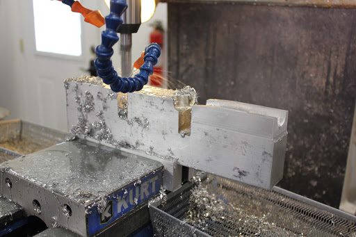
The 2 in segments are different from each other and have separate tool-paths for each one of them. The beginning segment has a 2.5 inch long, flat section that is used to clamp the tube to the bending die.
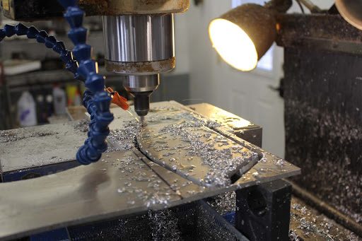
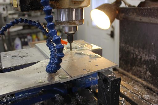
Cutting the attachment plates out of .25 inch aluminum
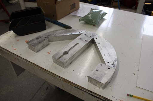
All of the segments completed and positioned in place
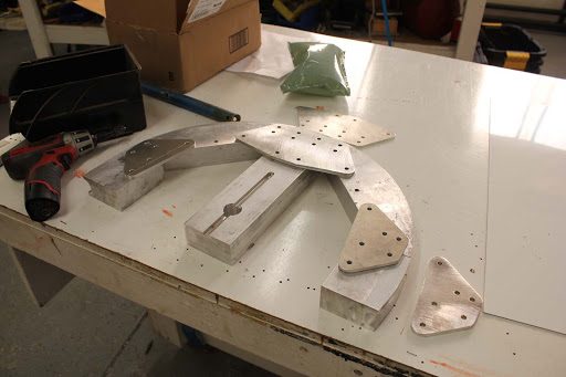
All of the plates are now manufactured.
8-22-2015
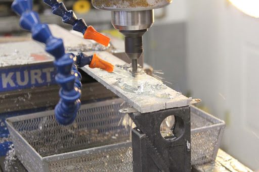
The last piece to manufacture is the cross tie bar which will support the bending dies during the bending process.
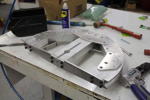
All of the pieces now complete and the individual pieces bolted together.
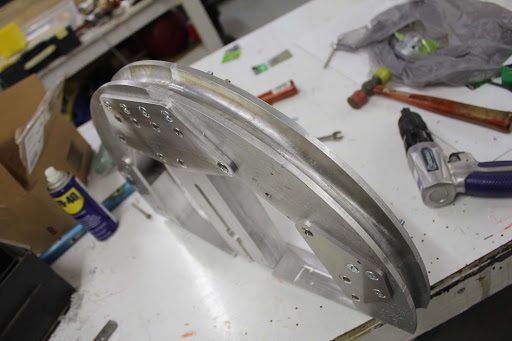
All of the radius die portions fit within a few thousandths of each other. Next step is simply to give this the test run on the Bending machine
8-23-2015
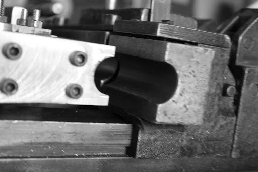
Upon initial installation in the bending machine. We found that the radius die, did not line up perfectly with the outer die clamping blocks and slider block.
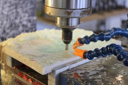
Next we had to manufacture spacers out of Corian to use to jack up the dies, so they were perfectly parallel. In this picture here we are pretty cutting the height so that the final part will come out to an exact thickness.
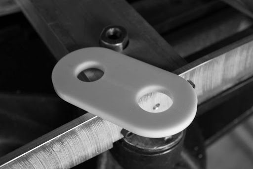
We ended up making 3 different spacers before we got one that was the perfect height. In this picture here you can see one of the spacers that will go underneath the 9 inch radius die.
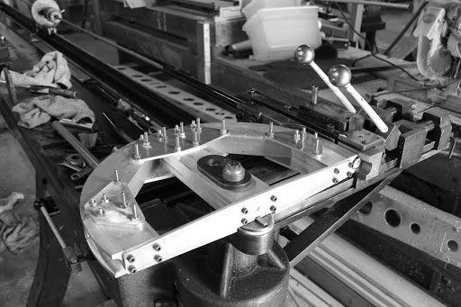
With the spacers installed and the test piece of 1 inch x .058 inch 6061 T6 positioned, everything lines up perfectly. It took several hours to manufacture some special holding fixtures for some of the slider dies.
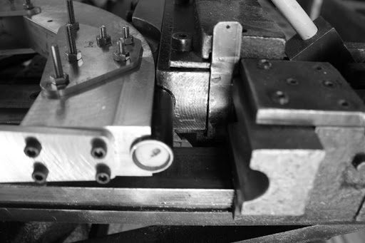
A picture of the 1 inch diameter tube in the 9 inch radius die with the clamp block moved out of the way so that we can see the orientation of the slider dies. The slider dies moves with the tube until it is about 1 inch past the bend axes.
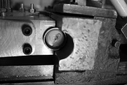
With this large radius die. We were able to manufacture a nylon mandrel that extends about 2 inches past the bend radius. This nylon remains in this position during the bending process but is pliable enough to conform to the tube inside diameter around the perimeter of the die during the bending process. This maintains the tubes concentricity and provides for a smoother bend by preventing the tube from collapsing during the bending process.
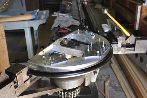
In this picture here we have bent a sample piece of tube 120° and then remove the clamping blocks preparing to remove the tube from the bending die
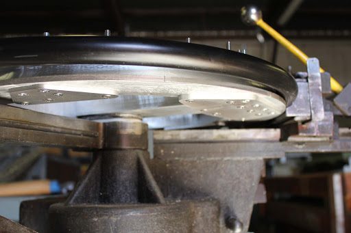
A look at the bottom side of the bending dies with the counter sunk screws to provide clearance from the base of the machine. In this picture here you can see the spacer underneath the keystone fitting.
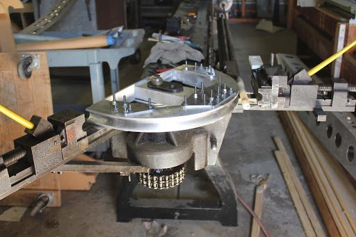
With the tube removed from the vending machine you can now see all of the components. The nylon plug that slides down the length of the tube on the inside which is held at the other end of an 8 foot long rod that attaches into a indexing collet.
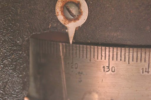
The machine has automatic bending stops built into the machine as well as 2 different graduated bending indicators. This one is on the front of the machine which is easily readable during the bending process
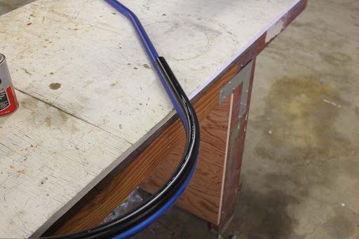
With the sample tube positioned next to the nose keel tube we see that the bend radius is nearly perfect.
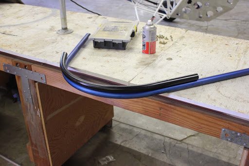
Now that we have verified the accuracy of the bending die. We can begin the setup process to duplicate components for mass production. In this picture here you can see that we didn’t bend the full extent of the nose keel but the radius is still showing the correct radius.
We will be adding more content as we continue the process of manufacturing the bending dies.