Shop notes · September 2015
EMG-6 "Shop Notes" September 2015
Brian Carpenter · Rainbow Aviation
September “Shop Notes”
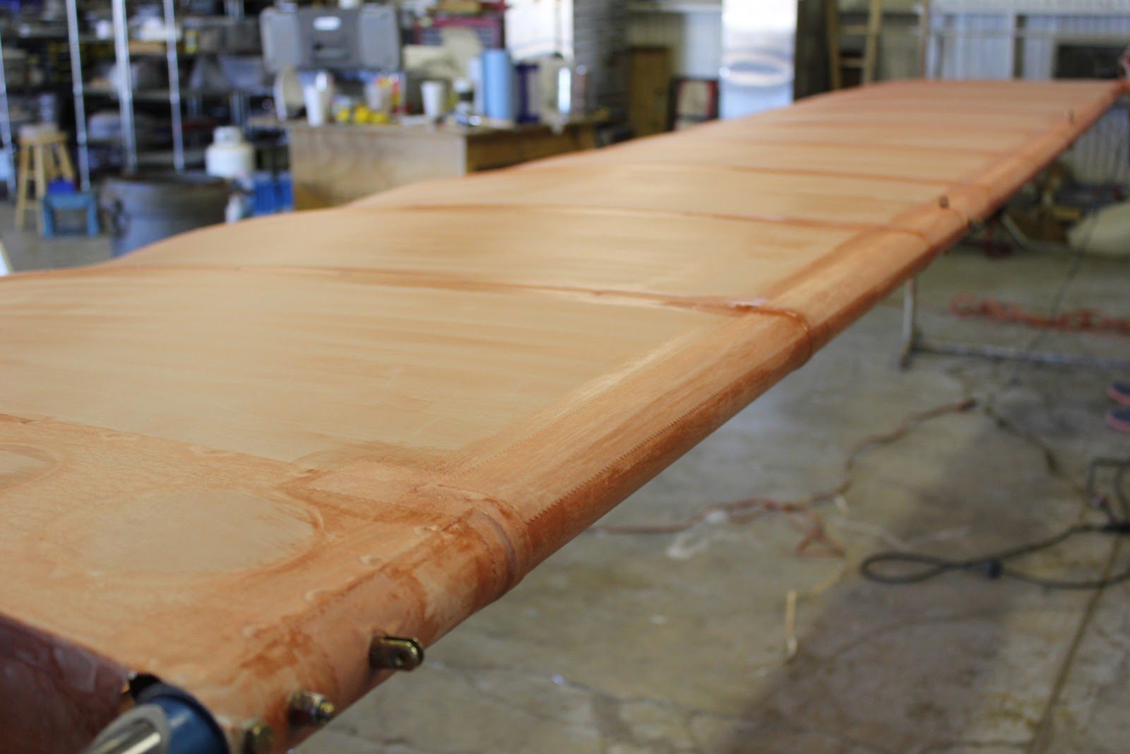
In this picture here we are starting on day two of the wing covering process.
The wing has set overnight and we can now start doing some of the finish tapes.
We should be able to finish up the left wing by this afternoon and get a start on the right wing.
During the construction process. We have been videotaping all of the process to produce a time lapse photography, video of the wing covering.
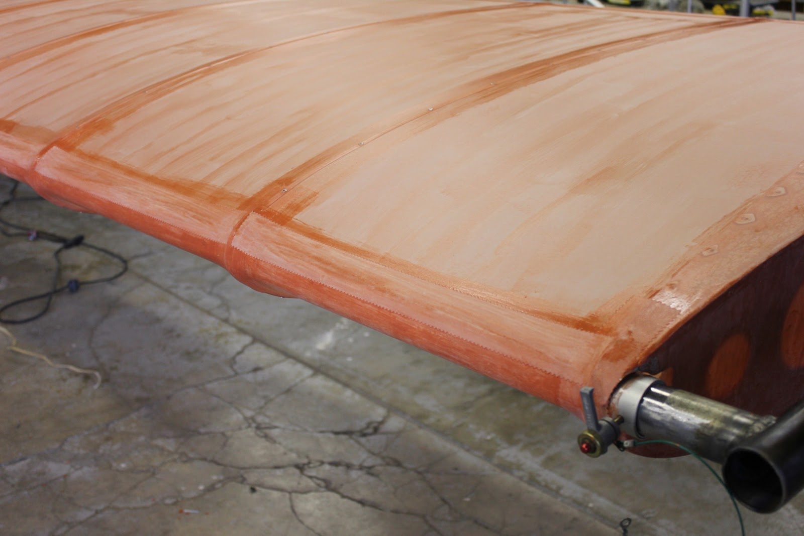
The overlap of the top fabric occurs on the bottom side of both the forward and aft spars.
In this case here were applying a 2 inch wide straight pink edge tape to the seams.
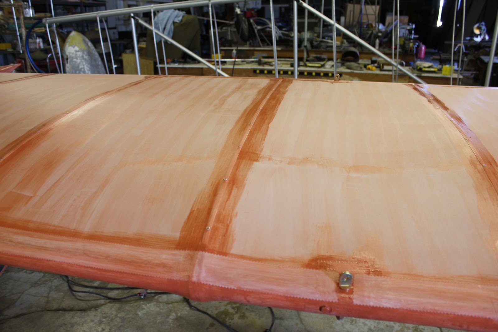
The last step in the process for the finished tape will be to cover the rivets and the reinforcing tapes at each rib.
We will be using a bias ply 2 inch wide pink edge tape to accomplish that.
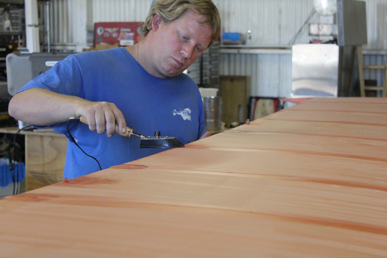
All of the edges of each piece of tape get a little treatment with the iron to flatten the edges as much as possible, which will reduce the amount of Sandy necessary when we get to the next stages of applying the poly spray.
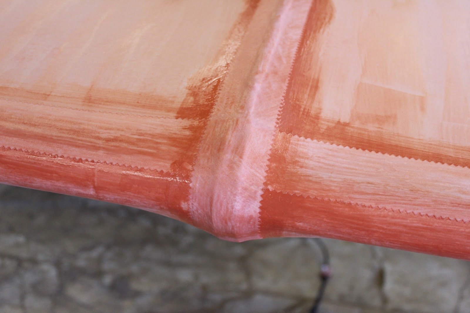
The bias ply pink edge tape’s at each rib. Start at the trailing edge and wrap around the entire wing back to the trailing edge. Once again, where it overlaps itself.
This also overlaps each one of the leading edge seam finish tapes.
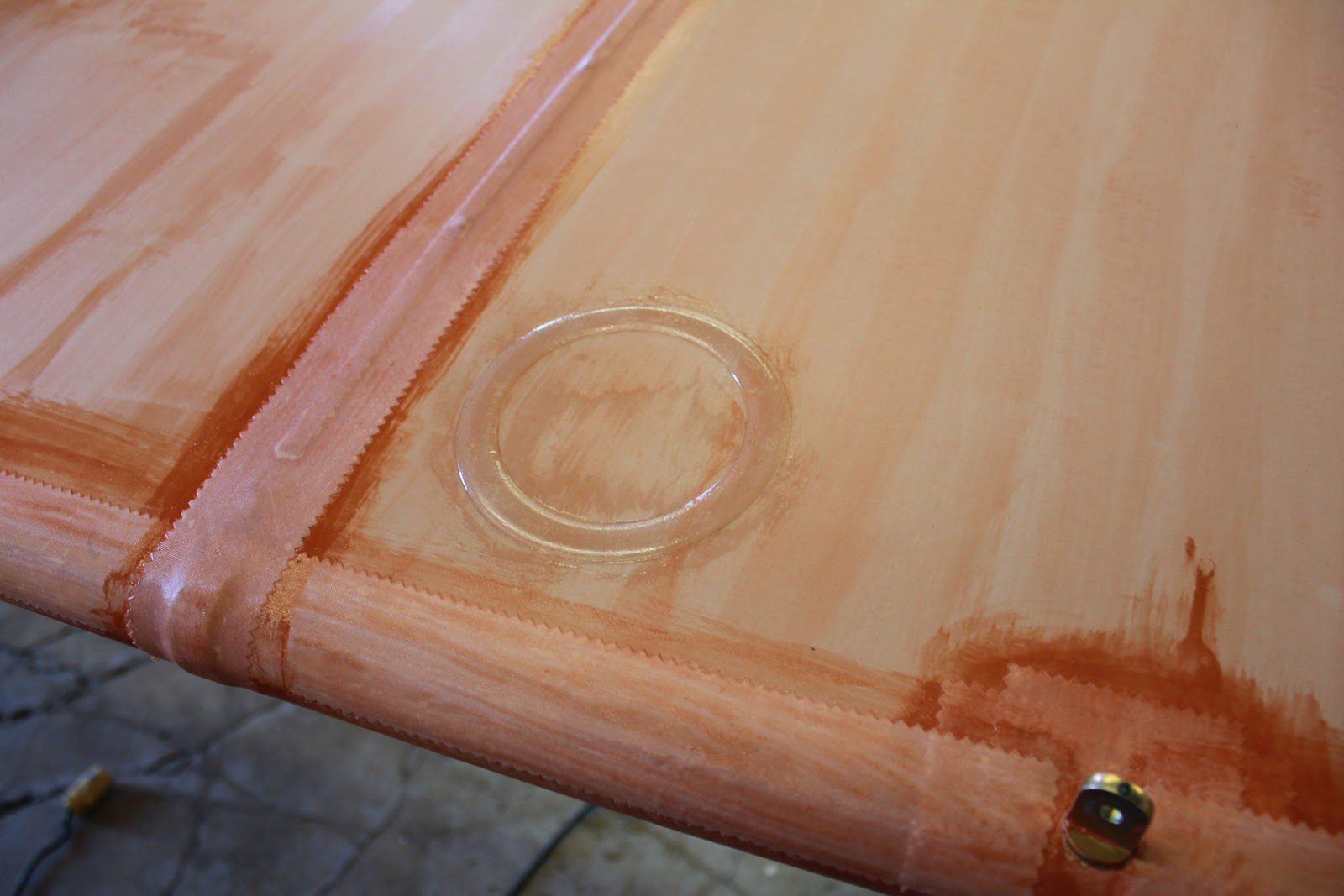
We also need to put in a a few inspection panels for later access to the inside of the wing for inspection purposes.
Because there is no internal mechanical components to the wing. There are only two locations where we will need inspection panels.
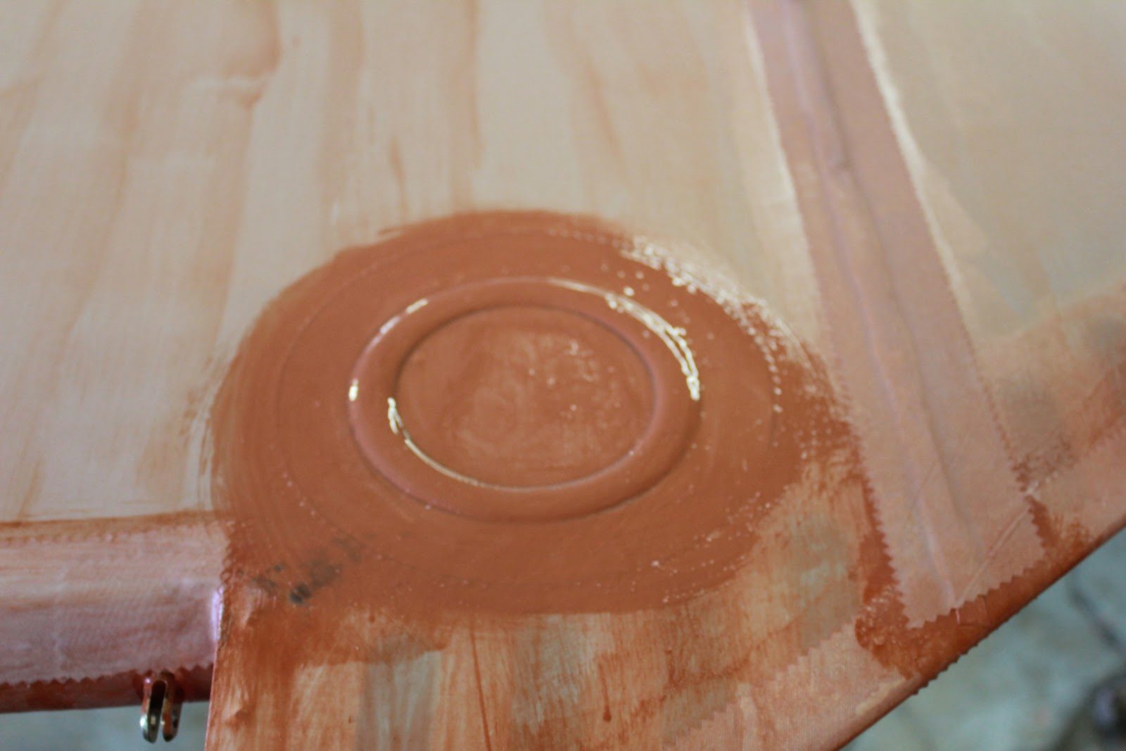
One of the inspection panels is located at the trailing edge near the wing tip.
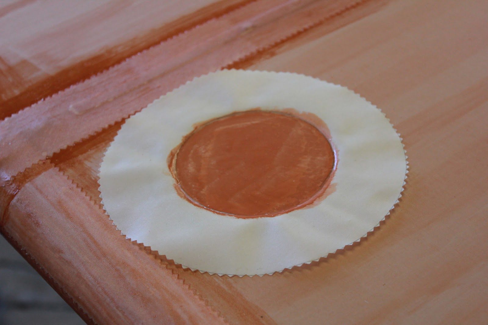
And the second inspection panel will be located at the trailing edge just inboard of the wing strut attach fitting.
We ran out of poly brush (the pink stuff). So we will not be able to continue on with the wings until that order of materials comes in. Probably later in the week or the first of next week.
September 28, 2015 Covering the Wings
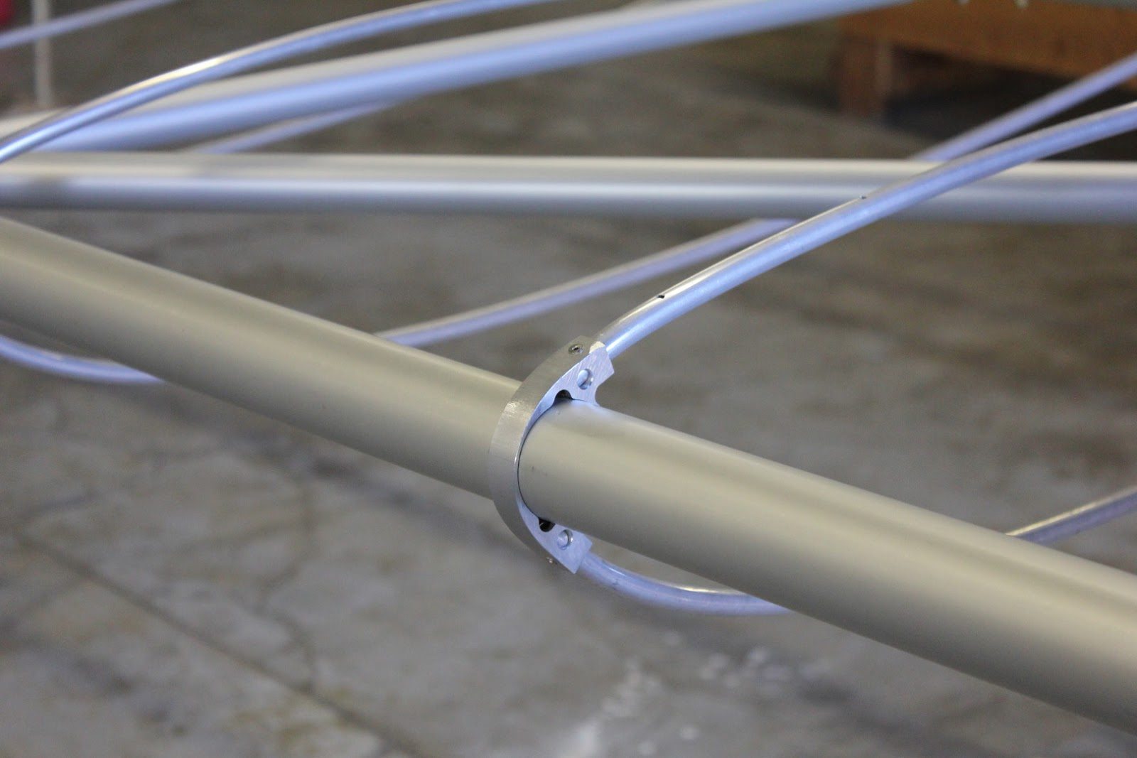
We have prepped the wings in their entirety.
Cleaning all of the aluminum components,
And drilling all of the holes for the fabric attach rivets.
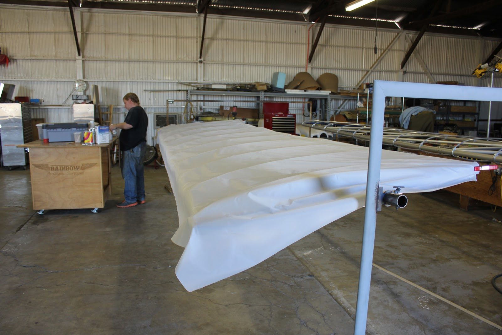
First step is to roll out the fabric to the length of the wing so that we are installing one complete piece per side.
This is 1.6 ounce Dacron glider cloth.
The big advantage of the glider cloth is it’s extremely easy to work with and super lightweight compared to the next heaviest fabric which is almost double the weight per yard.
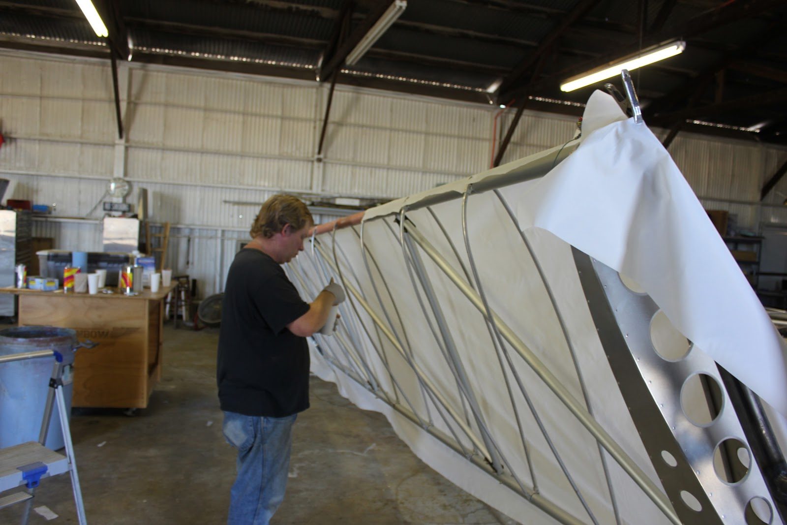
We start by attaching the fabric to the perimeter of the structure, starting with the bottom fabric first.
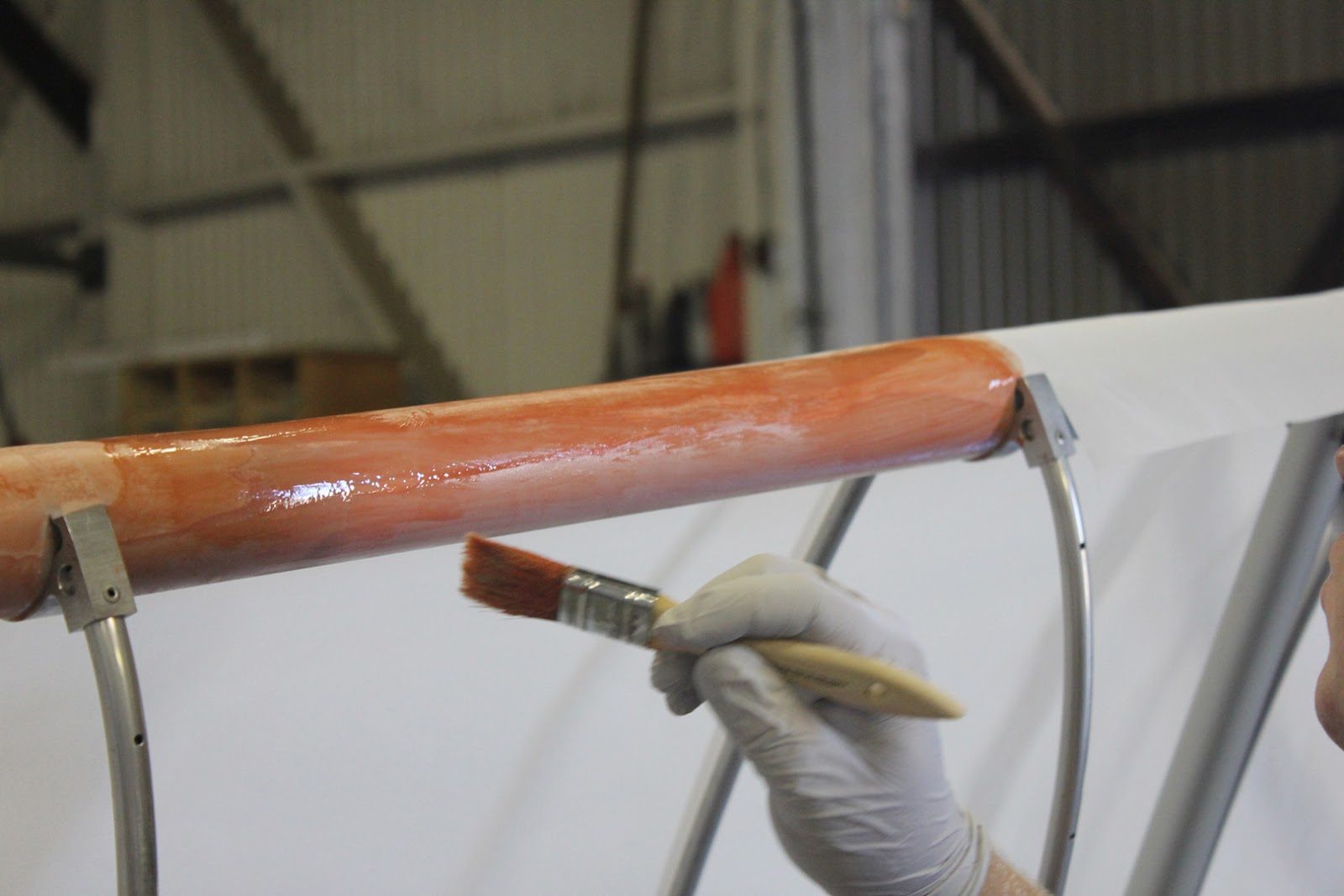
Using the poly brush on a very large surface, such as the leading edge tube gives lots of adhesion.
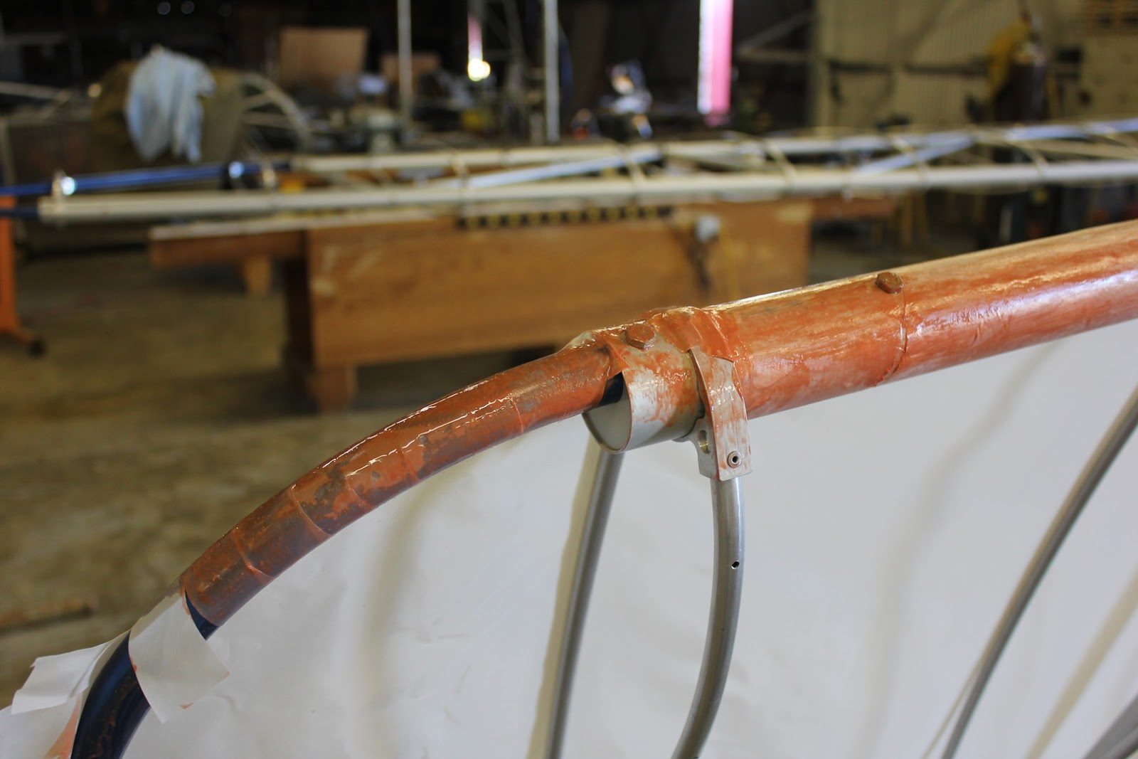
At the compound curves and the radius is we have to use a system of plates in order to be able to complete the round corners.
This will all be covered by a 2 inch wide bias ply tape after both sides of the fabric have been installed.
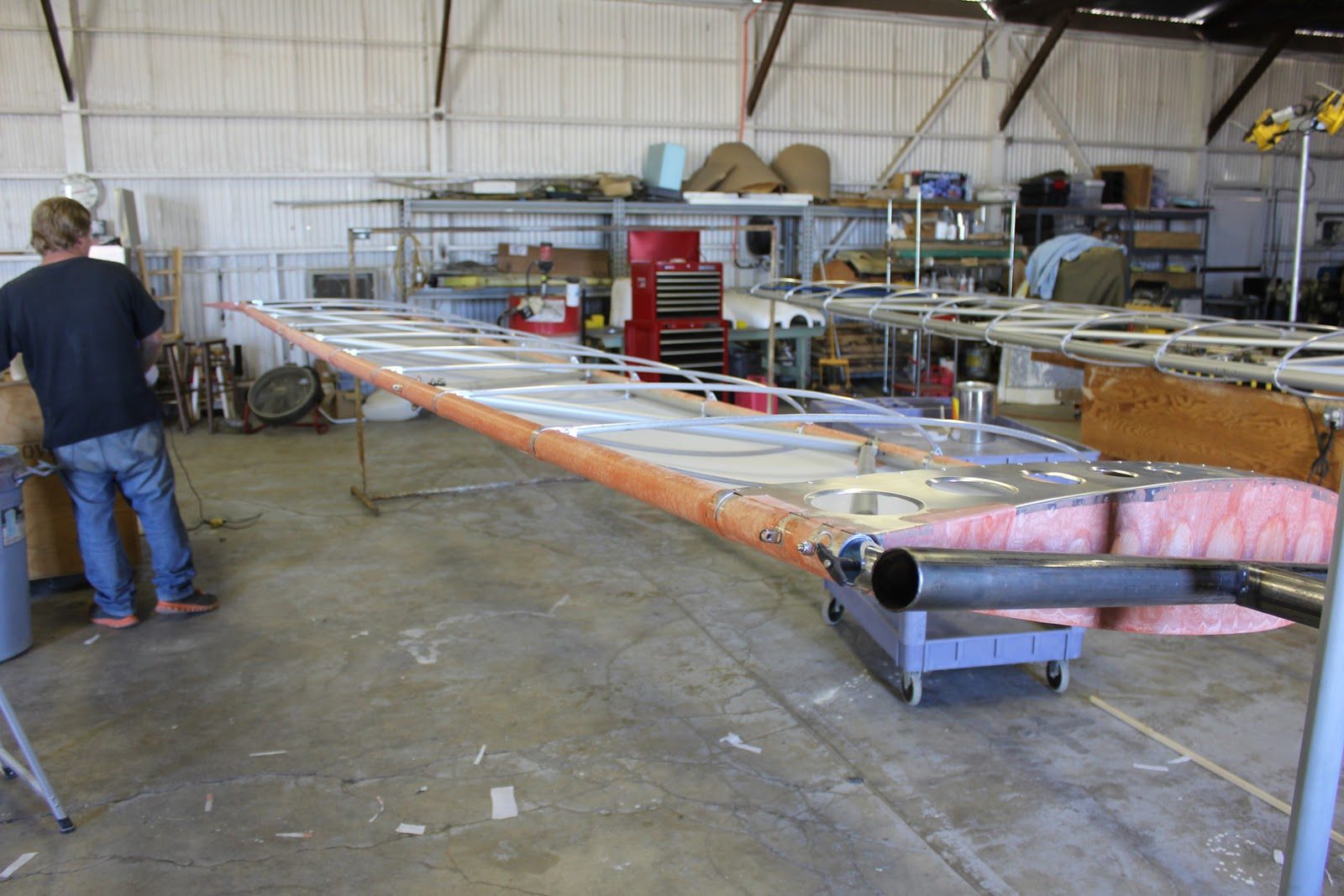
The advantage of having the rotating rack is that we can position that wing at any position during the covering process.
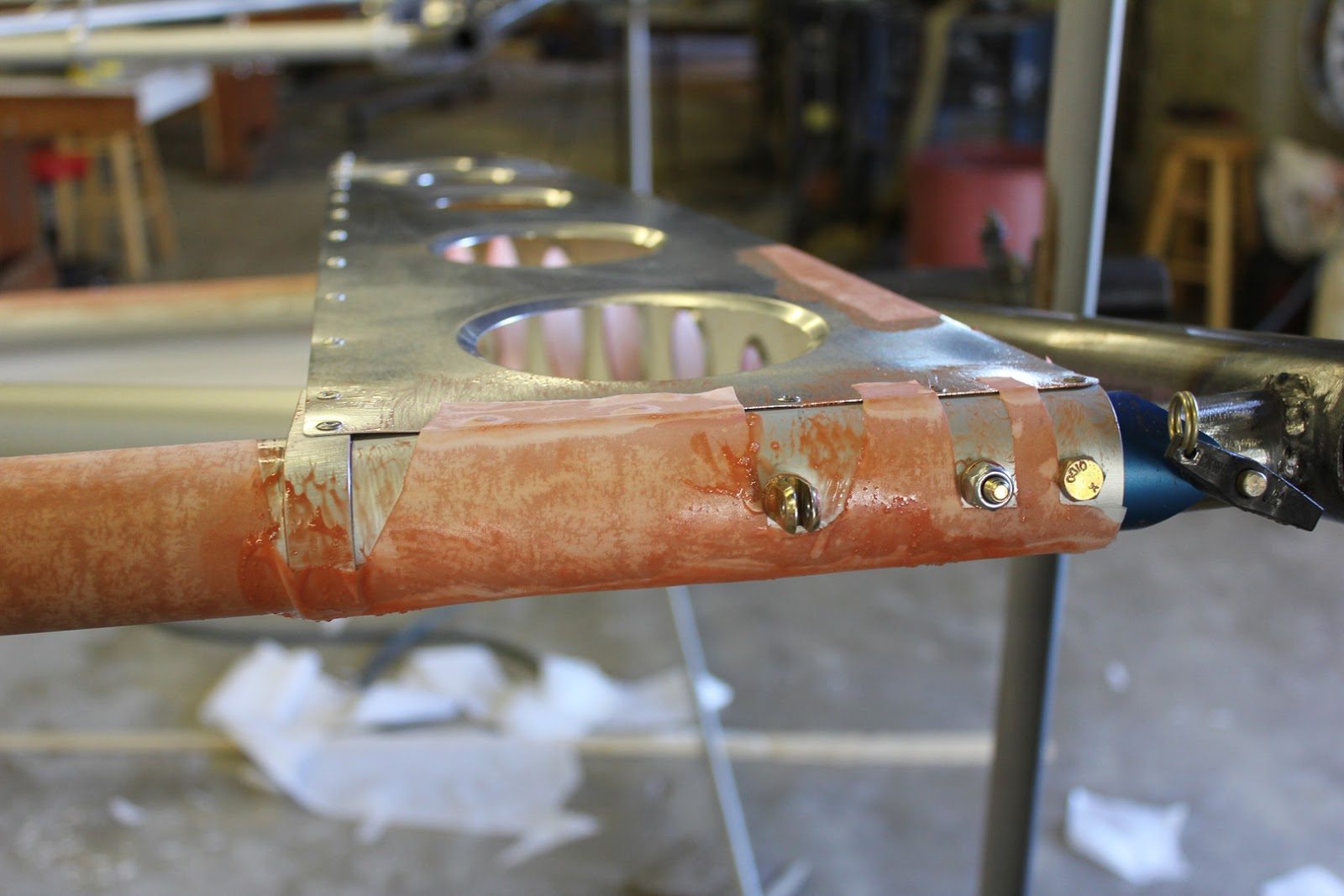
We are cutting out around each and every fastener, because we are trying to maintain exact orientation for the hinges and the fittings
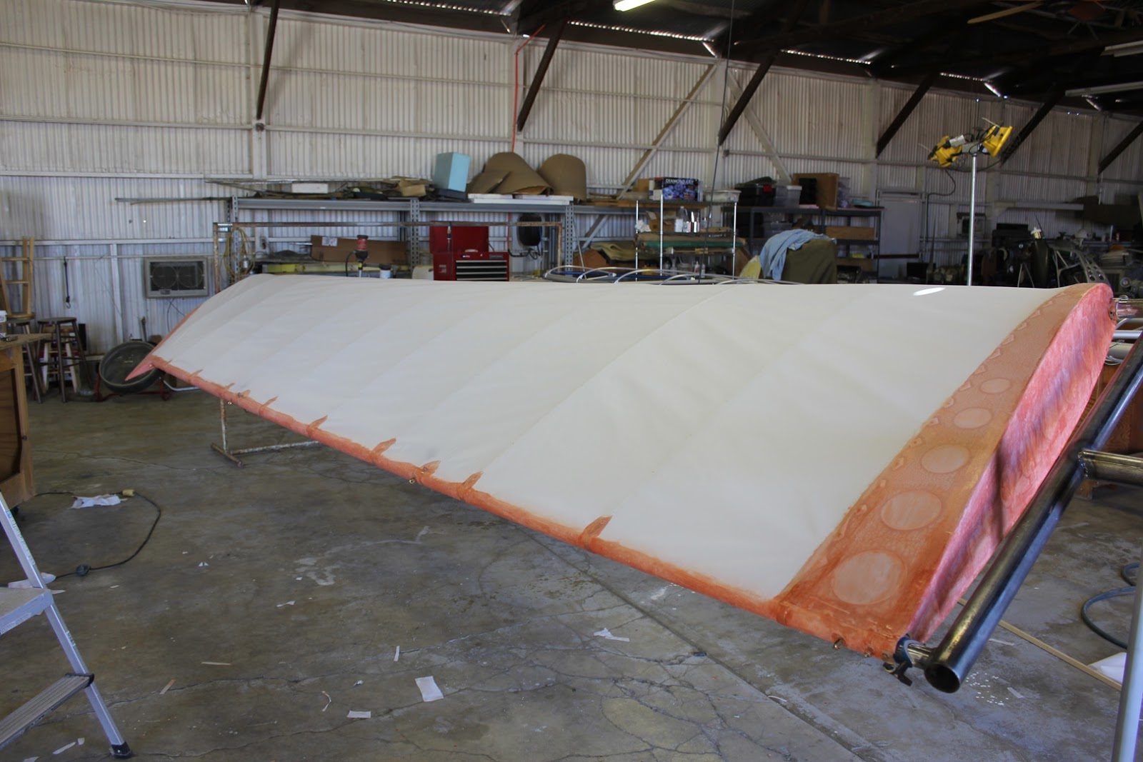
In this picture here you can see the bottom fabric has been installed completely.
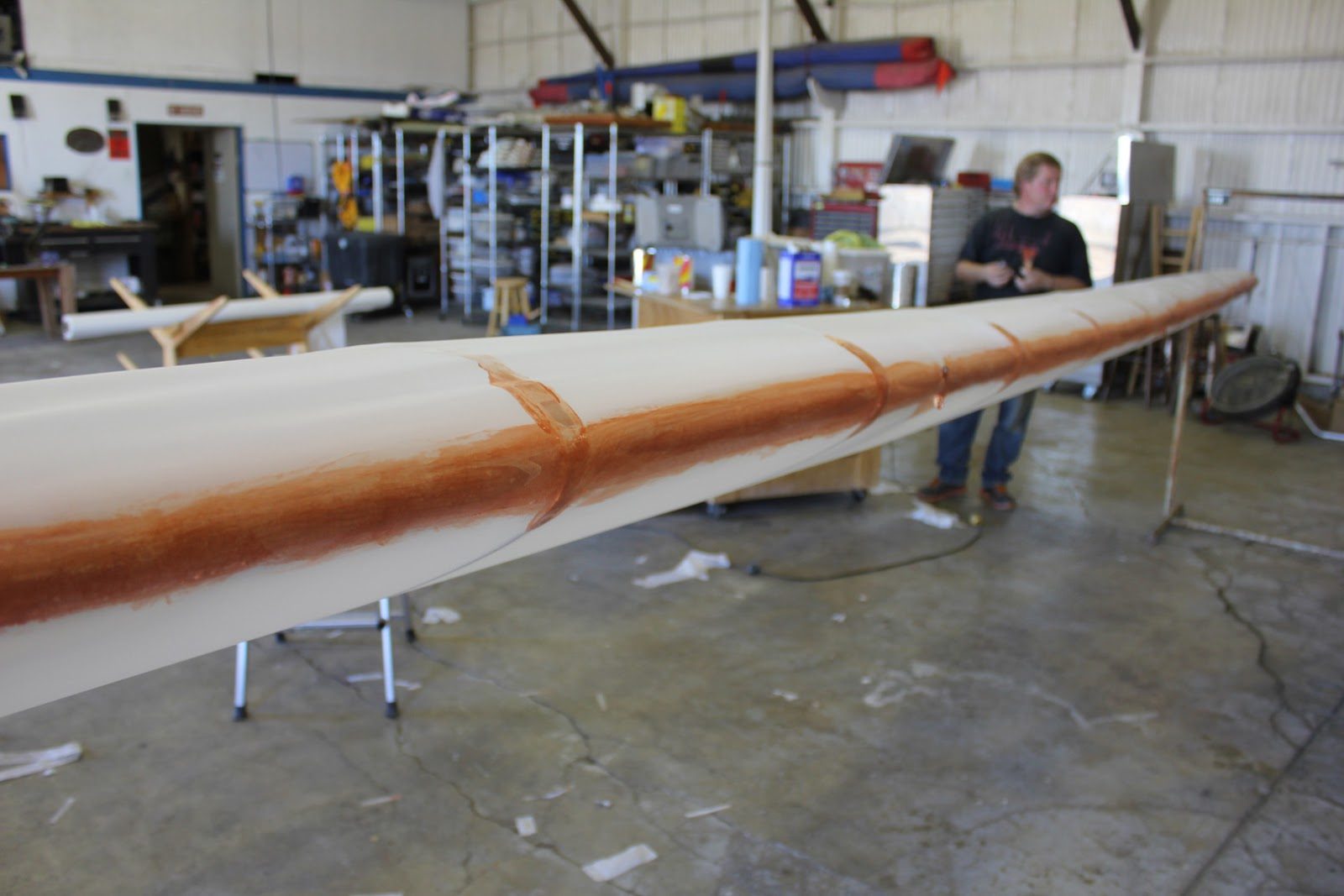
The top fabric now installed and the edges overlapped.
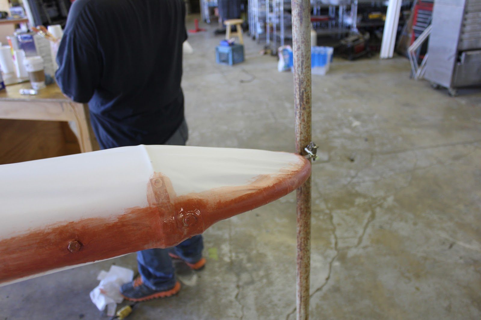
The compound curves of the wing tip can be a little bit tricky and require a little bit of preheating to shrink the fabric in order to eliminate any wrinkles.
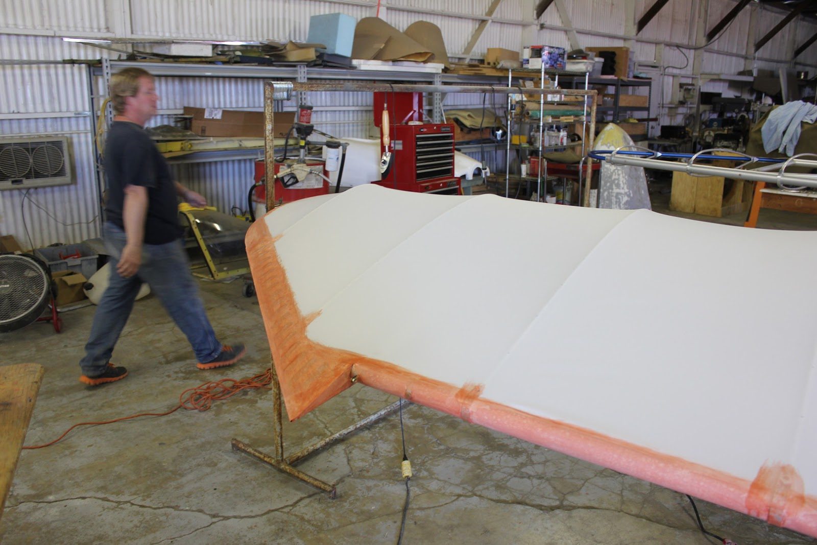
The new trailing edge design on the wingtip looks really good.
Should be considerably less drag them. The prototype aircraft.
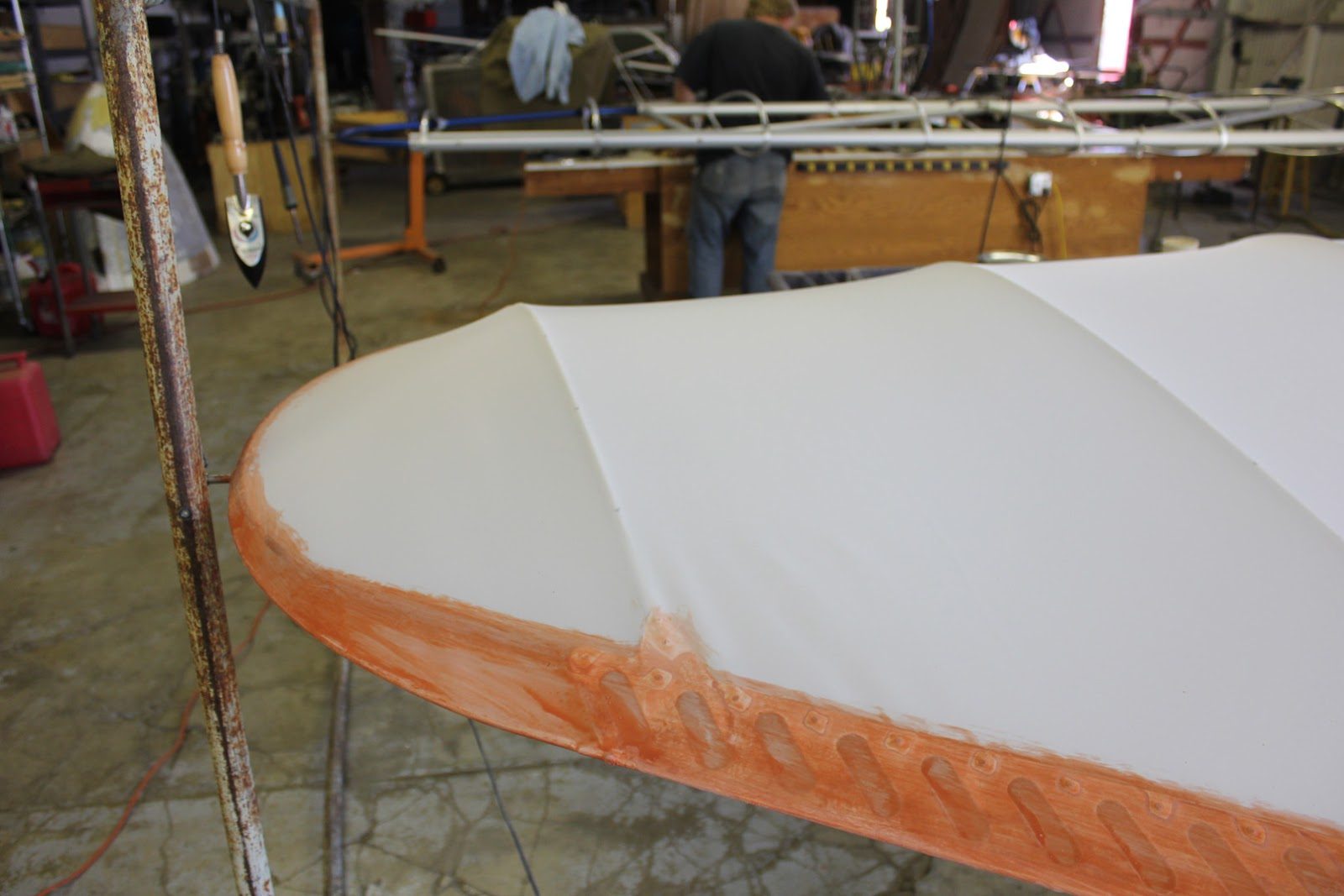
Also the wingtip ribs look really good.
It’s surprising that the amount a sag in between each rib was slightly more than we had anticipated.
This is one of the reasons that we went with the NACA 23015, airfoil for the ribs rather than the NACA 23012
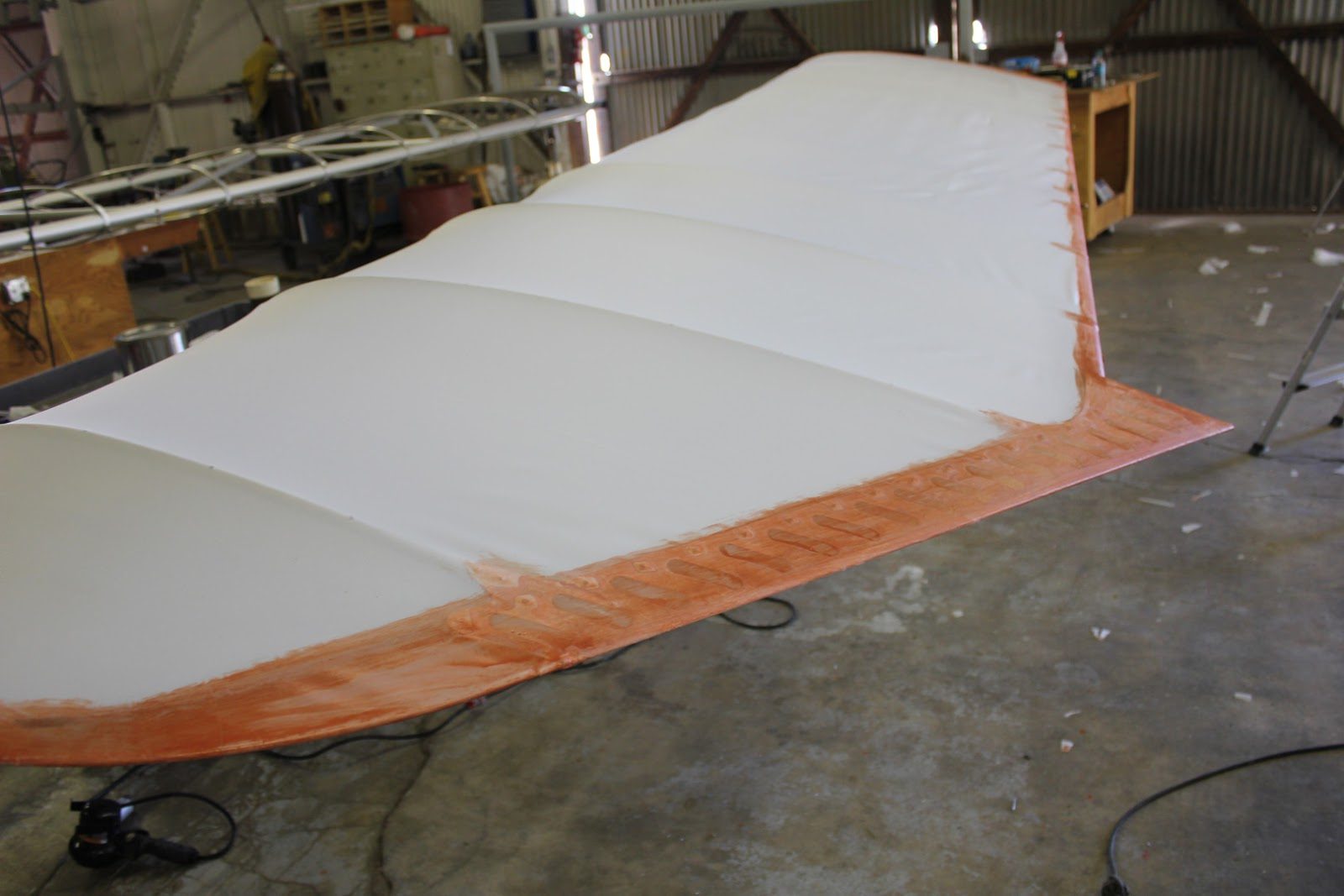
The outboard section of the wing has been slightly heated, where the inboard section has not yet been shrunk at all.
See a considerable difference between the shrunk in an shrunk sections of the wing.
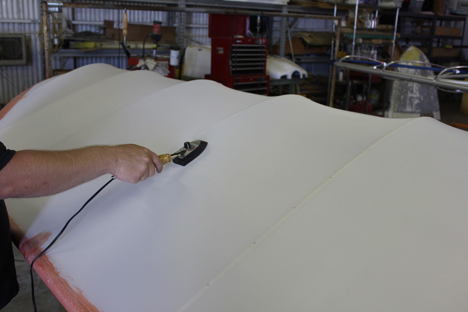
Initial shrinking of the fabric in order to achieve a well distributed shrinkage.
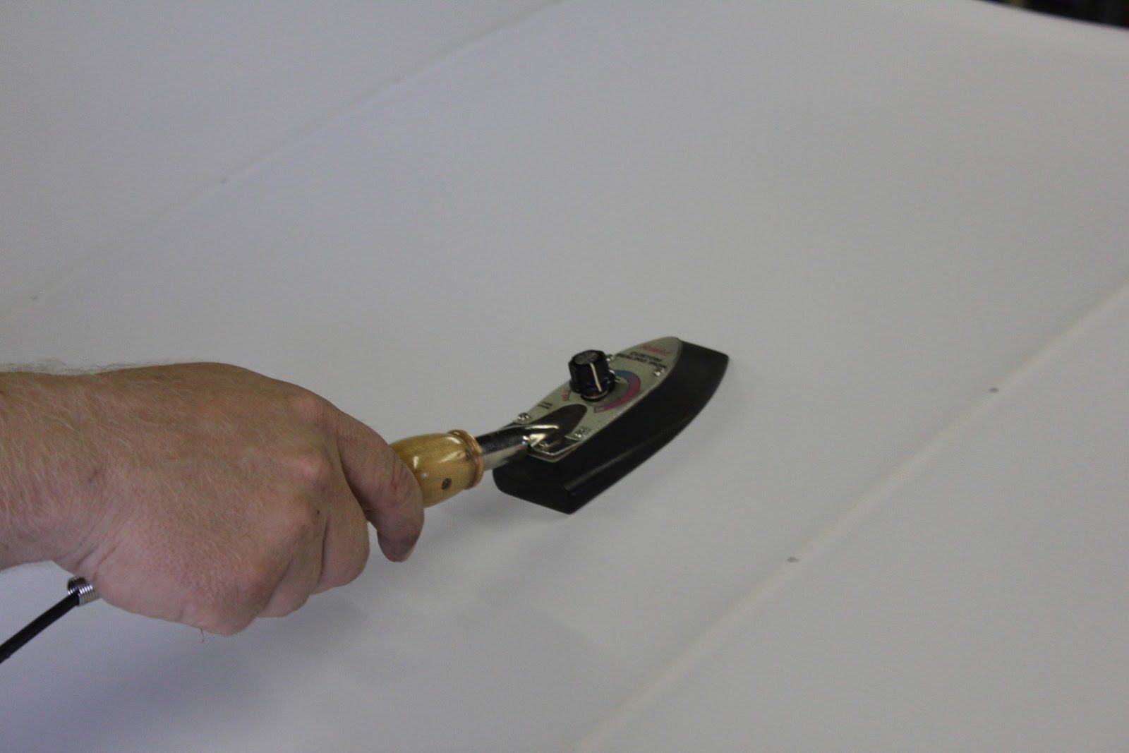
The final step is to stabilize the fabric with the iron set at 350°F and go over all sections of the fabric one step at a time.
This is a little bit tedious with a very small iron like we have here. But we like to use the small monocoque iron that is used for model airplane covering systems because it has a very stable thermostat and can control the temperature very accurately during the heating and shrinking process.
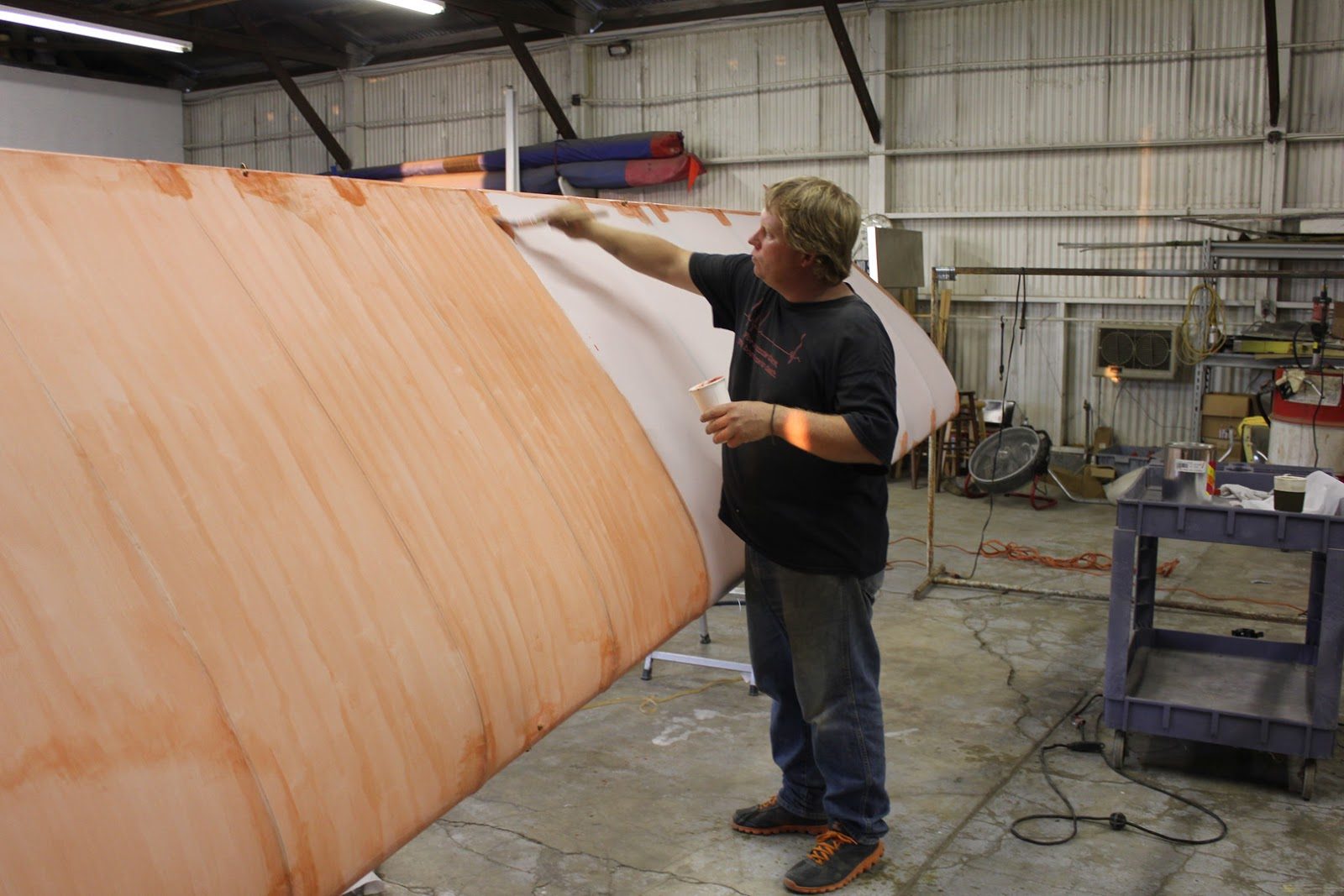
The next step in the process is to begin the poly brush covering with a nice 2-3 inch wide brush maintaining very parallel strokes.
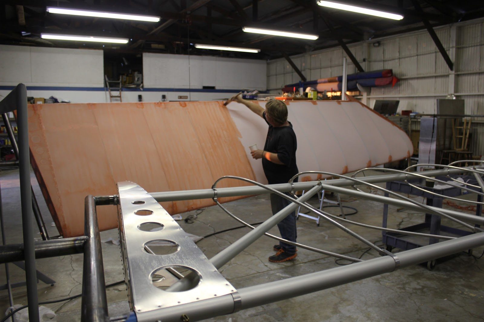
The covering with the brush actually takes about two hours to cover the whole wing.
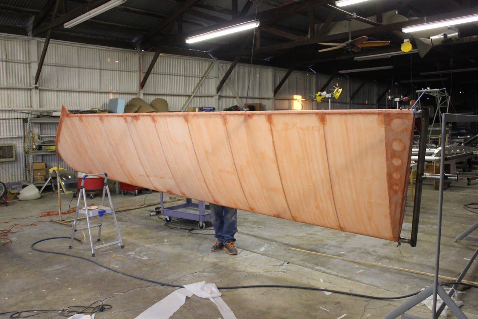
In this picture here we can see the bottom side of the wing has been completely covered and Jason is now working on the top side.
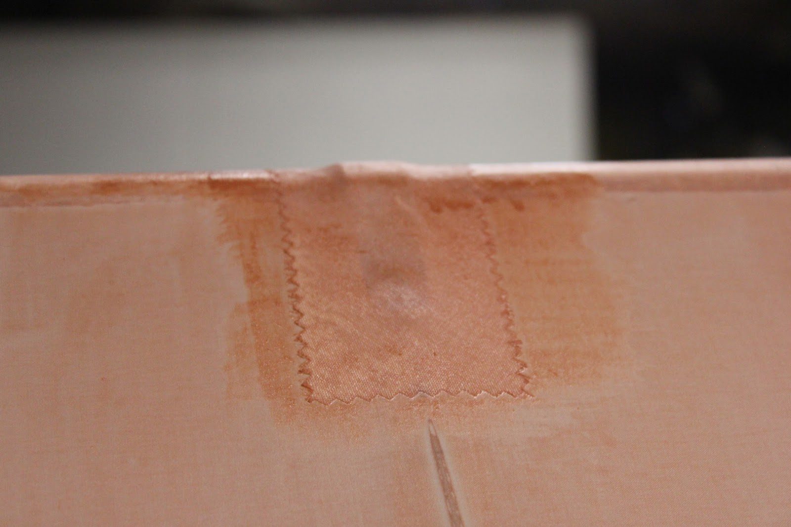
Every detail where there is a cutout or an overlap receives extra reinforcement. In this case here, where there is a slight compound curve. It requires the use of a pink edge bias ply tape.
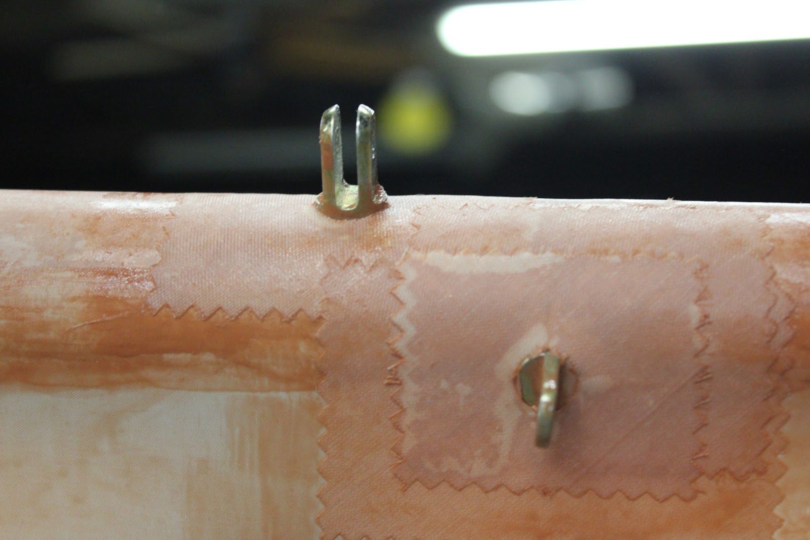
All of the bolt holes, Eye Bolts, fork bolts Get two additional reinforcement layers around the perimeter. This will allow for removal, or maintenance of these fasteners. Later on.
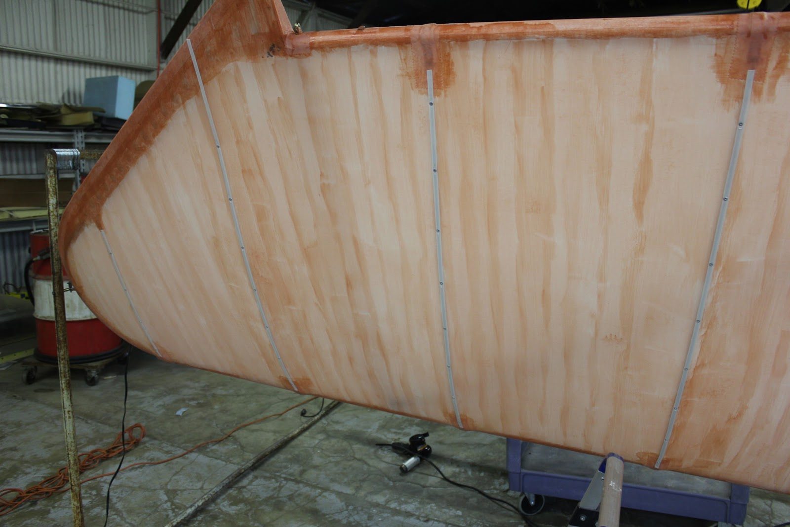
The next step is to install the reinforcing tape set each rib.
Remember that we predrilled each one of the ribs with a very specific spacing pattern.
We install the reinforcing tape which is 3/8 of an inch wide, and then we pierce the reinforcing tape and install a an aluminum pop rivet into each one of these locations.
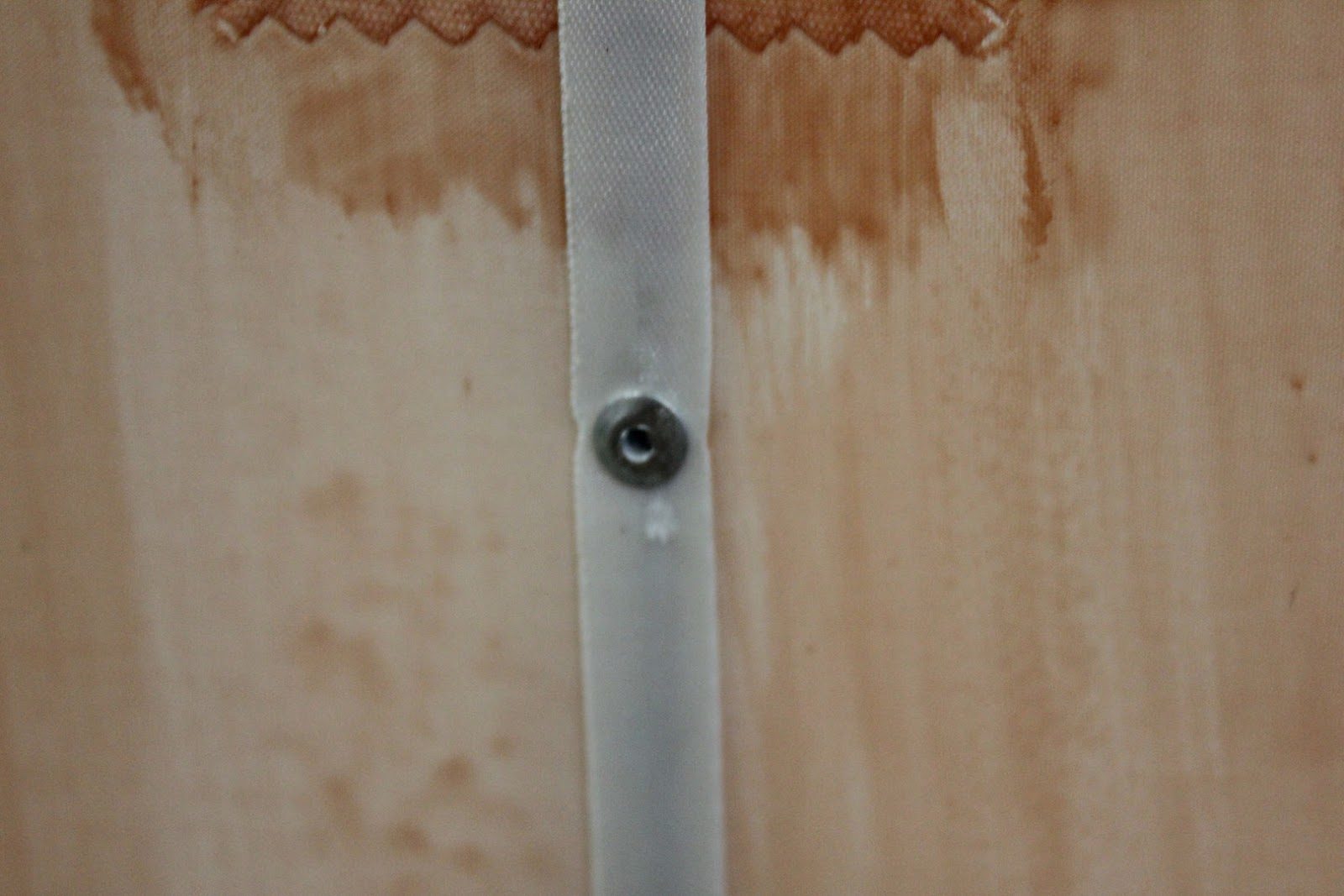
With the reinforcing tape permanently installed on to the rib with an aluminum pop rivet it will provide greater adhesion of the fabric to the rib structure.
This is the equivalent of rib stitching. But goes much quicker.
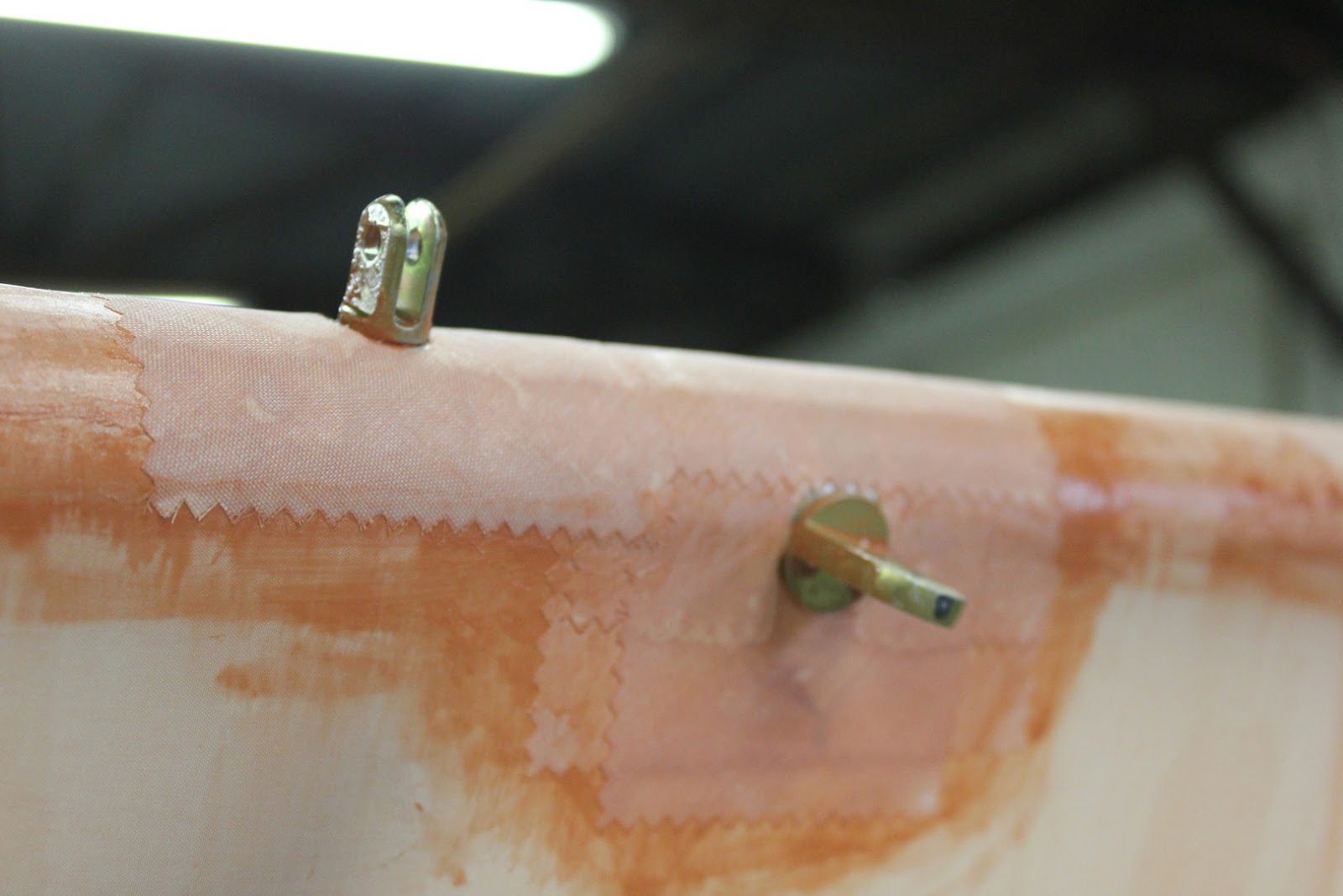
More reinforcing tape’s around the hardware that sticks out of the structure.
We are almost finished with the basic covering of one wing, and we did all of that in a single day.
September 24, 2015 Prepping the Wings for Covering
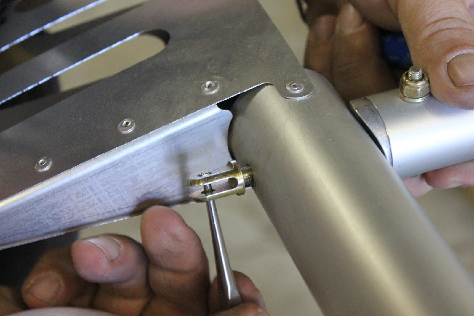
Before the wings can be covered all of the fittings that attach the compression struts from the forward spar to the rear spar have to be removed and reinstalled with Blue Loctite and then torqued to 30 inch pounds.
In this picture here. This is the outboard wing tip hinge bolt that doubles as the bolt that attaches the compression struts together.
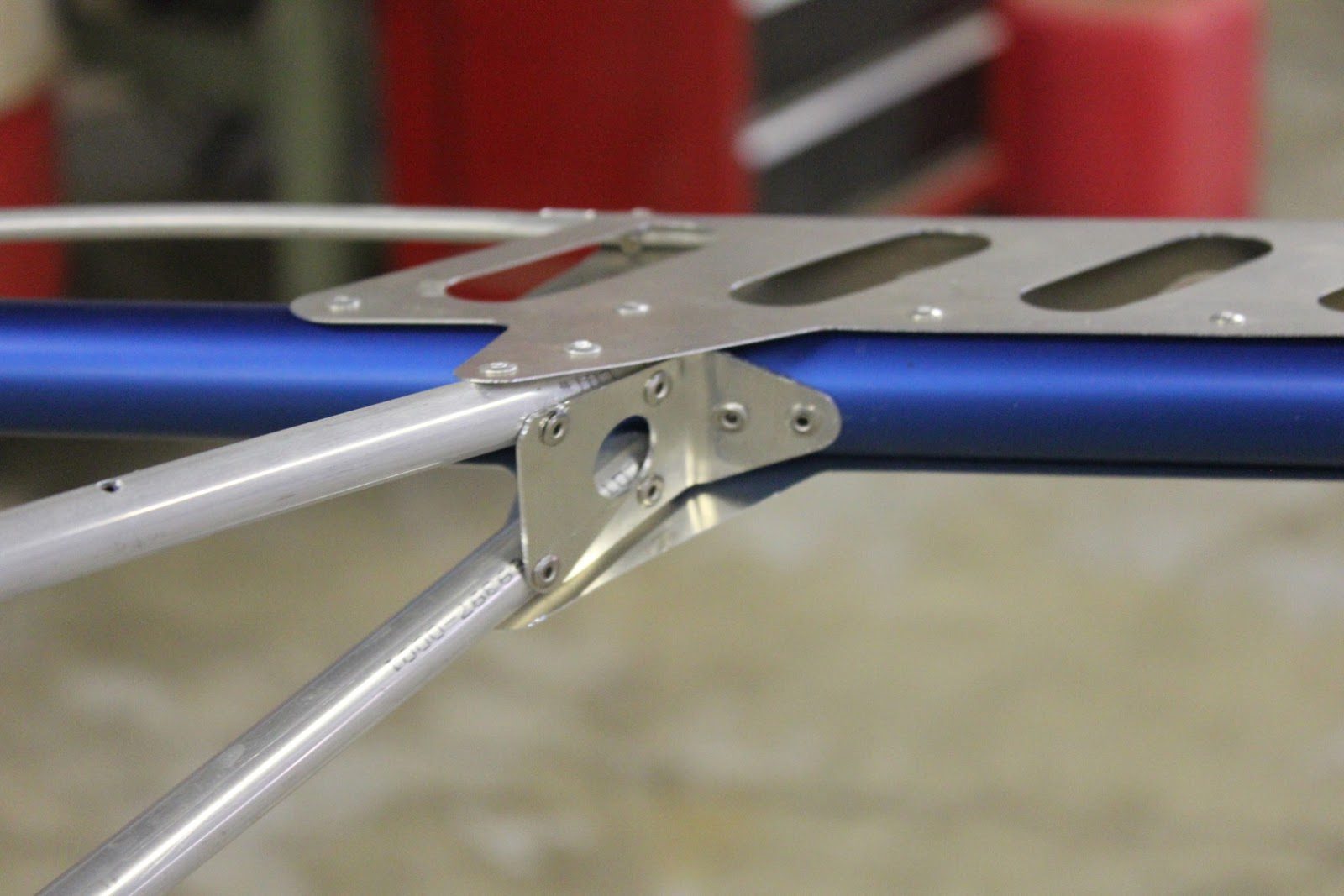
The two outboard wing ribs to not have socket fittings like the forward and rear spar is because of the smaller 1 inch diameter wing tip tube.
In order to strengthen this rib. Section a small clip is installed from the ribs to the wing tip bow.
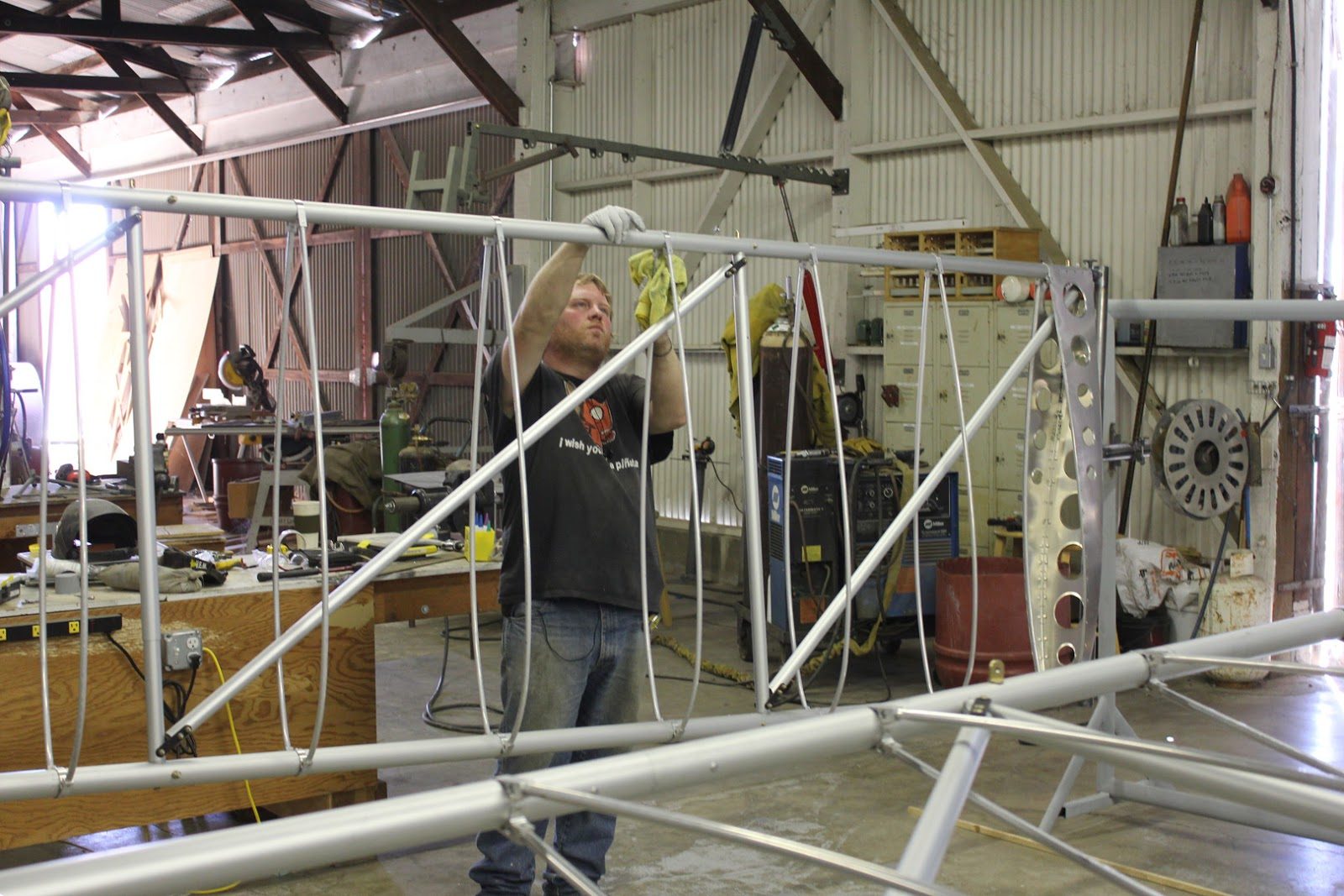
The entire wing needs to be cleaned with acetone prior to covering. Any of the ink marks left on the tubing from the manufacturing process that identifies the type and material of tubing will bleed through the fabric.
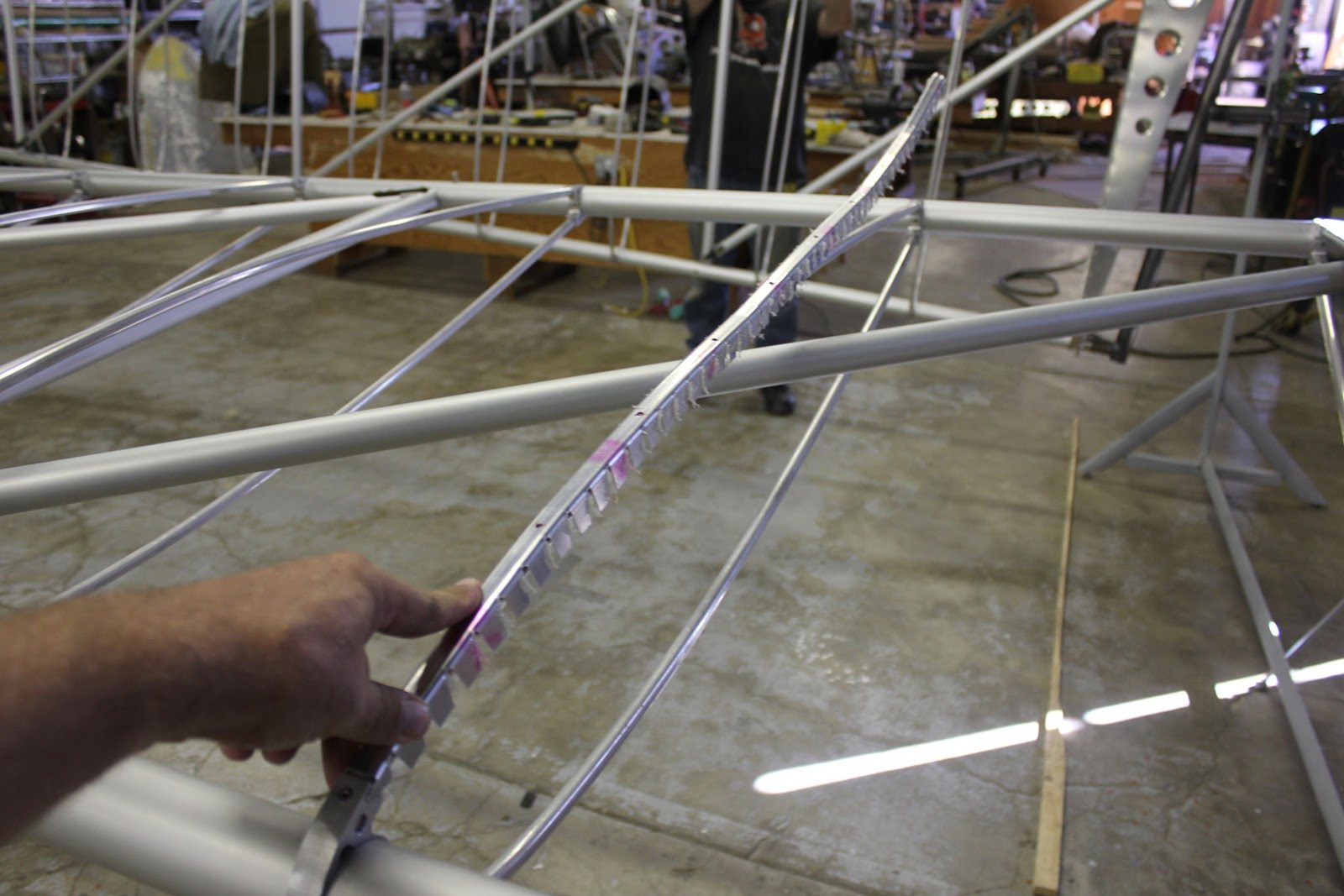
We have a wing rib marking template that fits over the top of each tube with holes strategically placed at 5 inch intervals, which makes identical marking for the fabric rivets to be installed in a very distinct pattern.
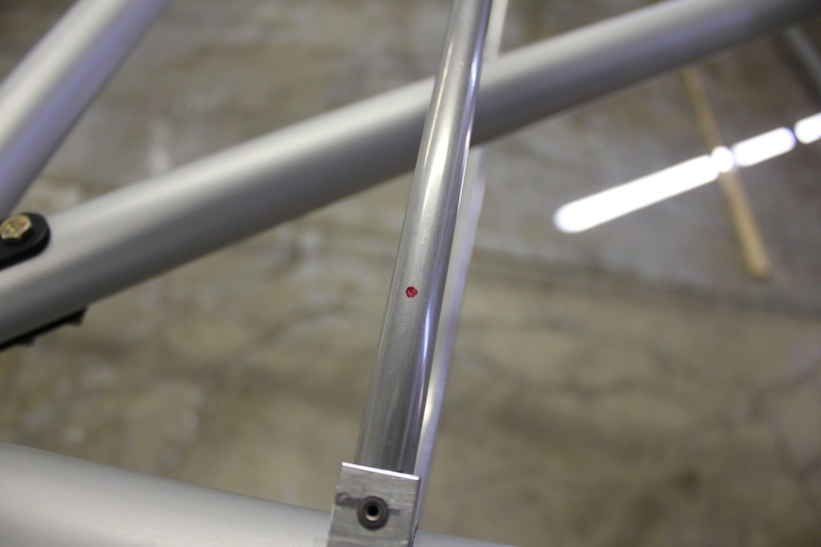
A magic marker is used to Mark each one of the rivet holes.
The rivets will take the place of the rib stitching on this wing and will make for a very reliable, simple method of attaching the wing skin to the ribs.
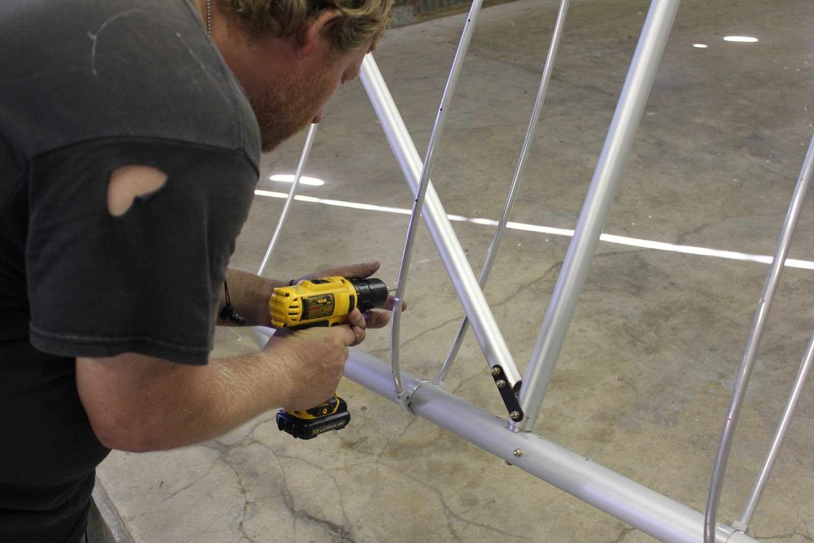
After all of the ribs both top and bottom have been marked we will drill at a #30 hole For each one of the fabric rivets.
September 23, 2015 Wing Holding Jigs Completed
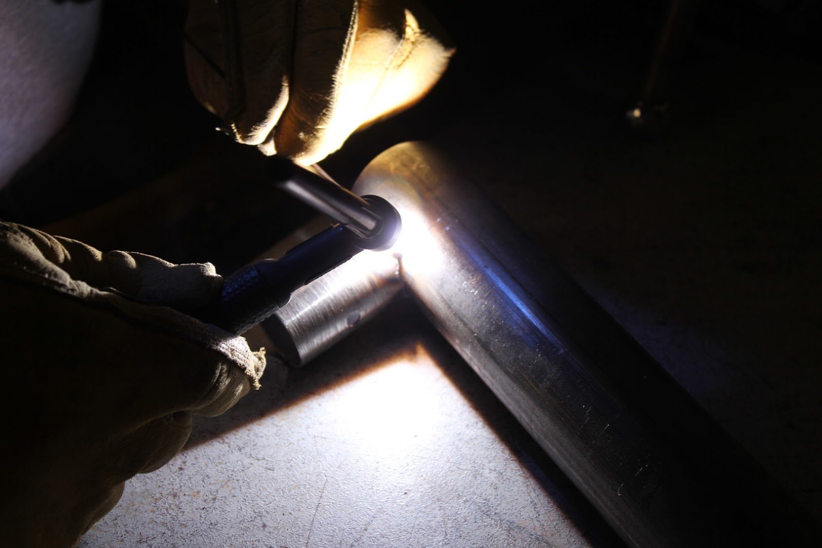
Welding up the fittings for the right wing fixture.
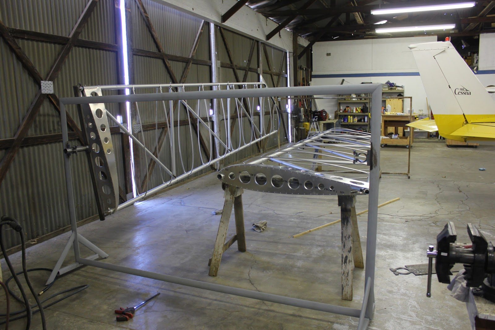
The left wing is hanging on the fixture and we are almost ready to hang the right wing.
The balance of the wings are nearly perfect. Even without the holding clamps tightened the wings will hold position where we rotate them to.
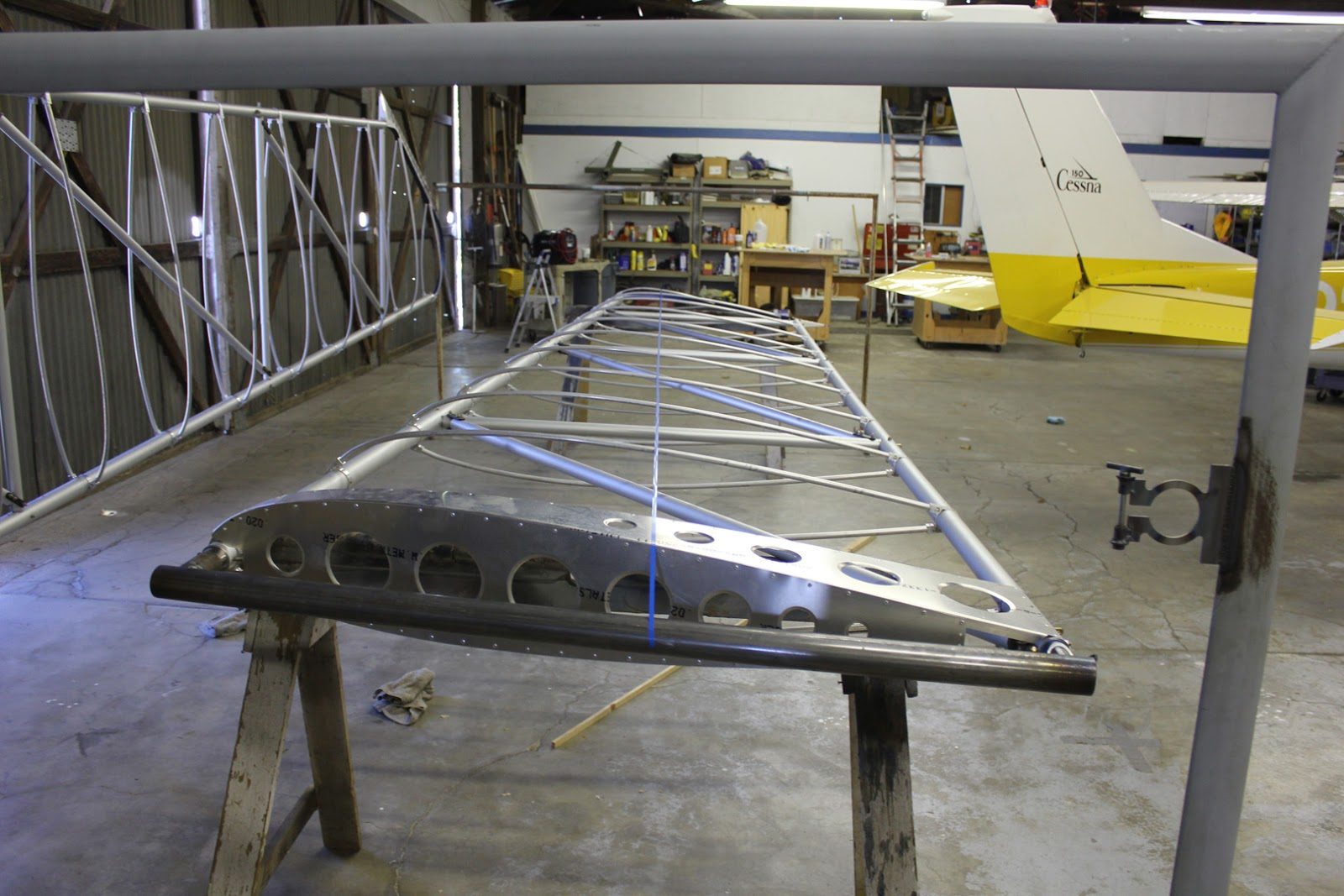
The alignment tape from the tip to the pivot for the right-hand wing.
This is what balances the wing is properly positioning the fixture related to the center of gravity.
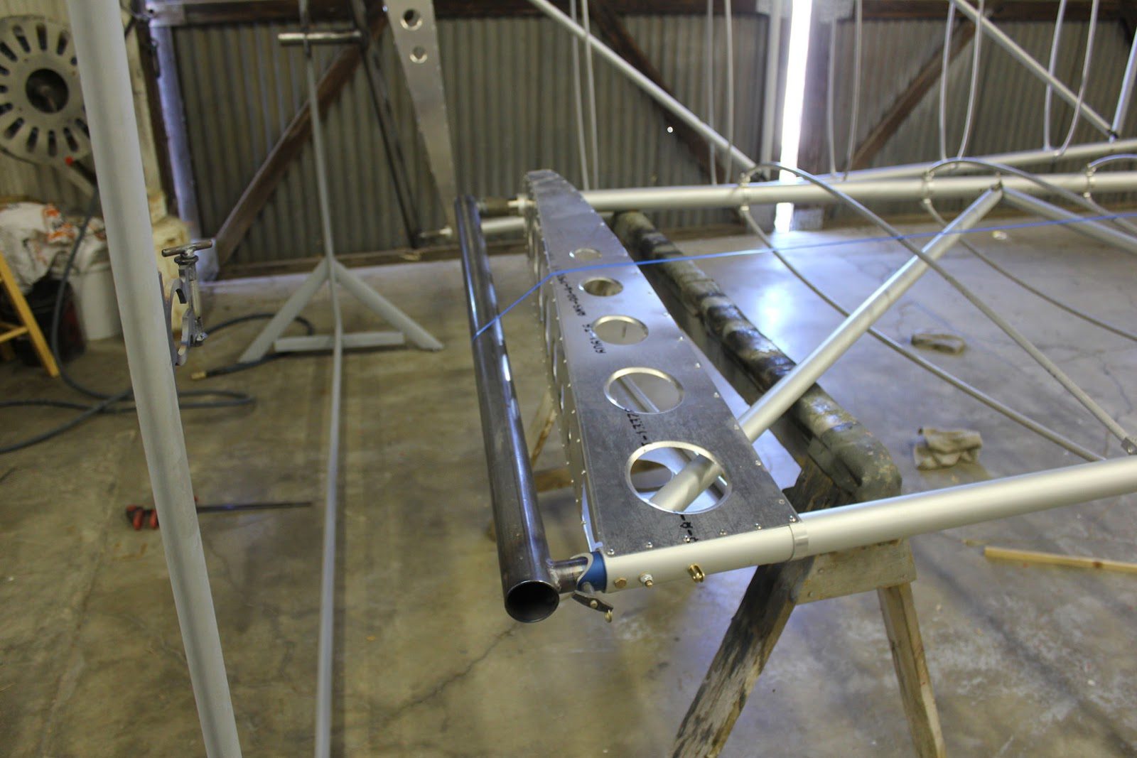
The right wing inboard fitting complete and ready for the pivot arm.
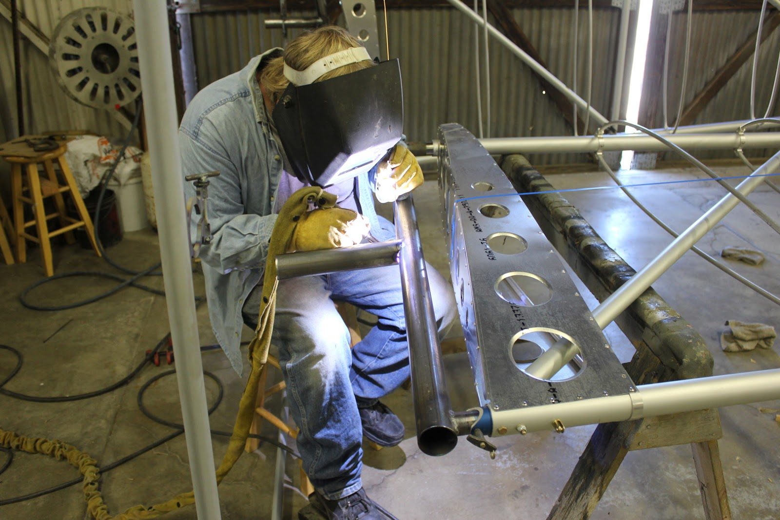
Pivot arm being tack welded in place and then double checked for alignment.
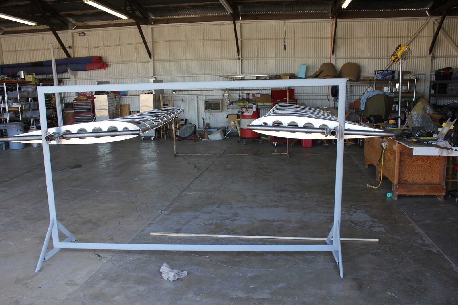
Both wings laid out on the rack in the horizontal position.
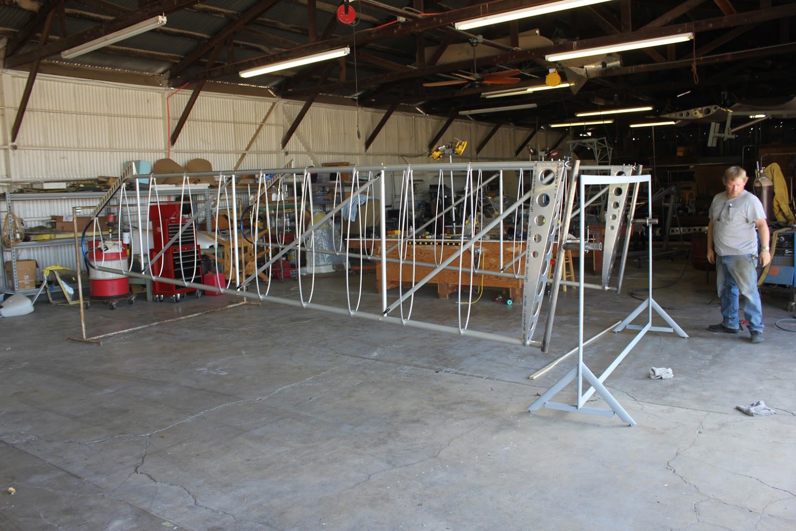
And the wings rotated to the vertical position.
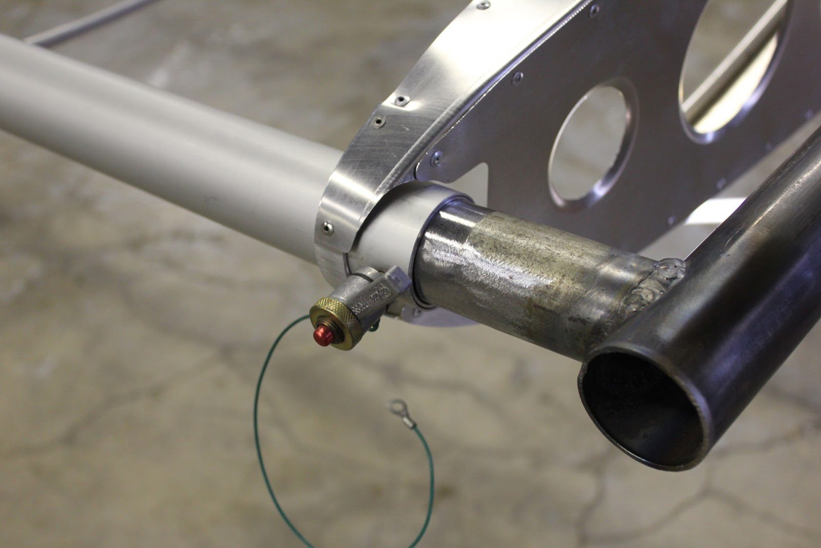
Quick release pins for the wing attachment
September 21, 2015 Continued Progress on the Wing Holding Jigs

In this picture here. Jason is welding up the inboard fixture that will allow the wing to rotate once installed on the fixture.
The fittings are tack welded in place while on the wing to ensure accuracy of the fit.
The fit becomes fairly critical because of the 3° taper Built into the spars.
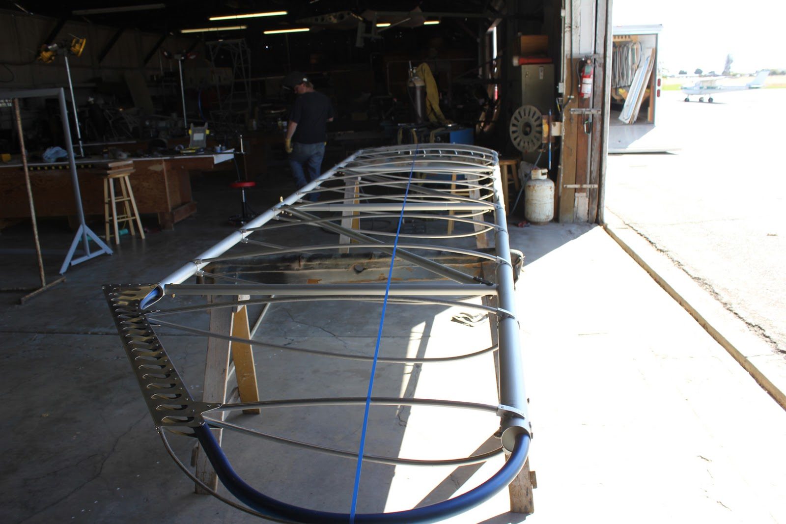
.
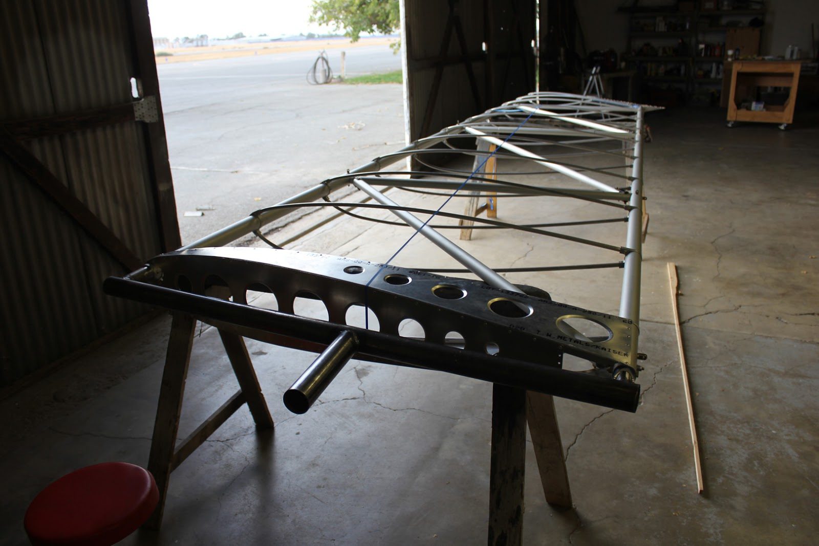
The wingtip has a fixed location, which we can rotate the wing around which is located slightly forward of the center of gravity.
And since the wing will need to be balanced and have both pivot points at the root and the wingtip on the same axis we balanced the wing in the covering configuration and strong a blue tape line to use as an alignment guide during the installation of the inboard fixture axle.
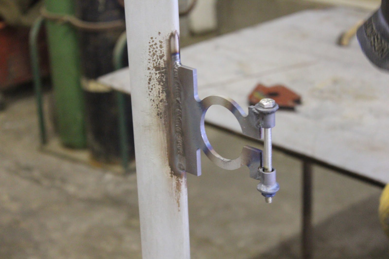
The inboard axle mount is designed with a clamping mechanism that will allow us to position the wing in any position and then clamp it from rotating while were working on the wing.
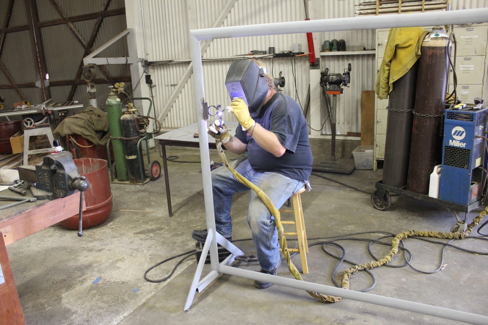
In this picture Jason is welding. The inboard axle mount.
Positioning and tack welding. The inboard axle in alignment with our marking tape.
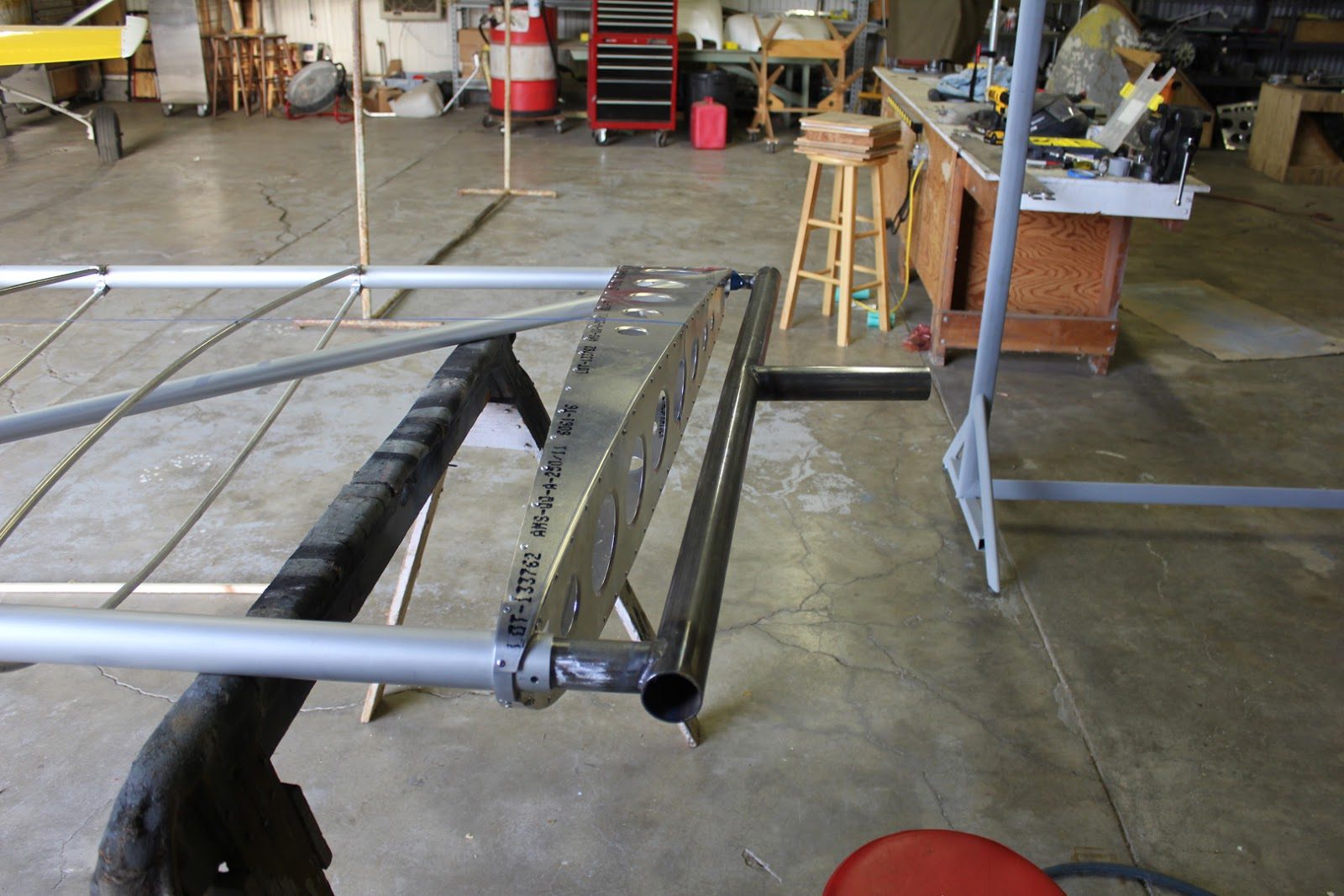
A look at the inboard mounting fixture.
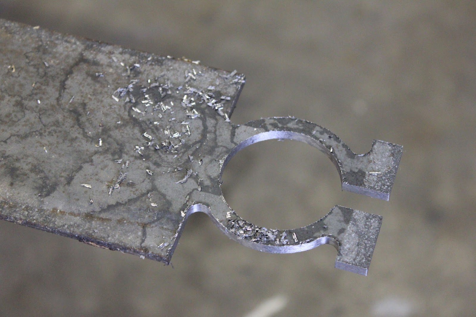
The CNC machined out inboard axle mounting plate.
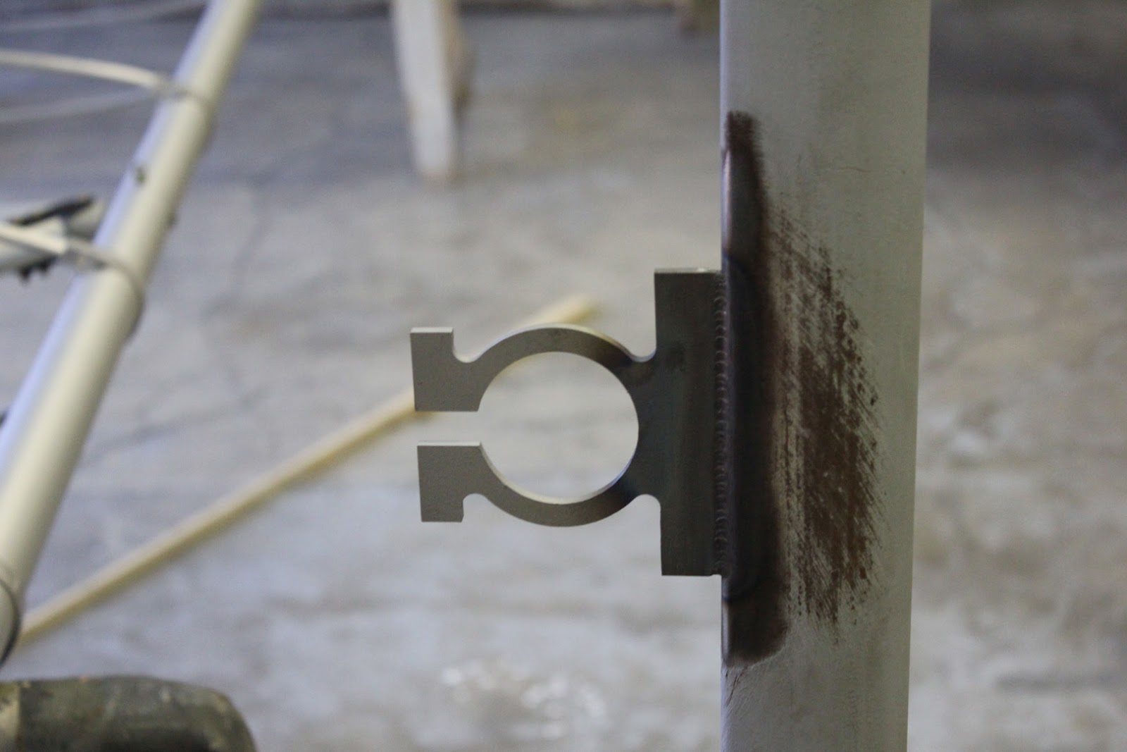
The mounting plate for the right side welded into position
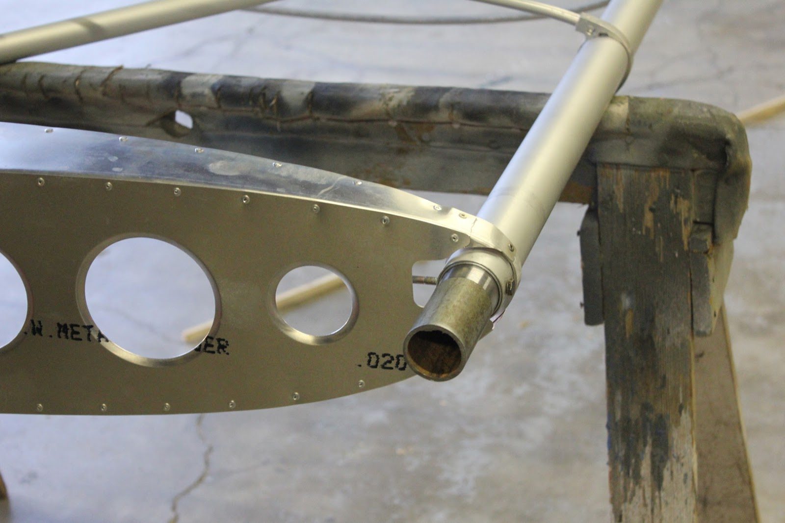
Duplicating the fittings for the right Wing. We start with a stub and a centerline hold drilled through the stub to hold the wing spar in position
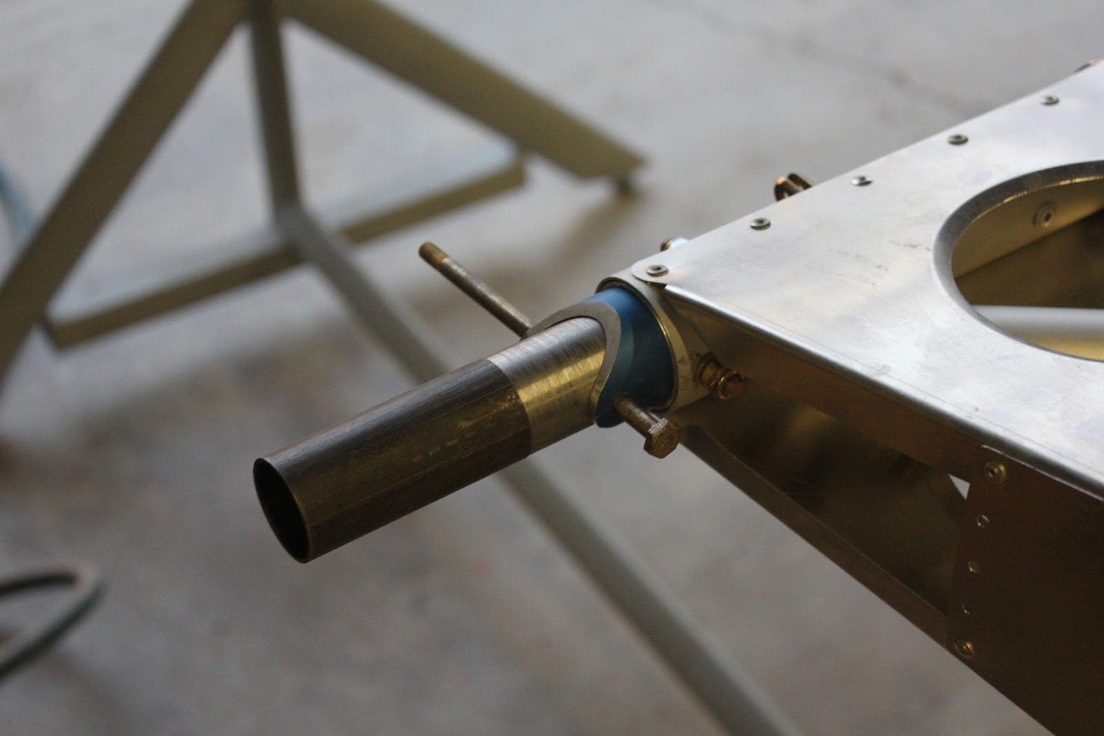
The same process happens for the rear spar.
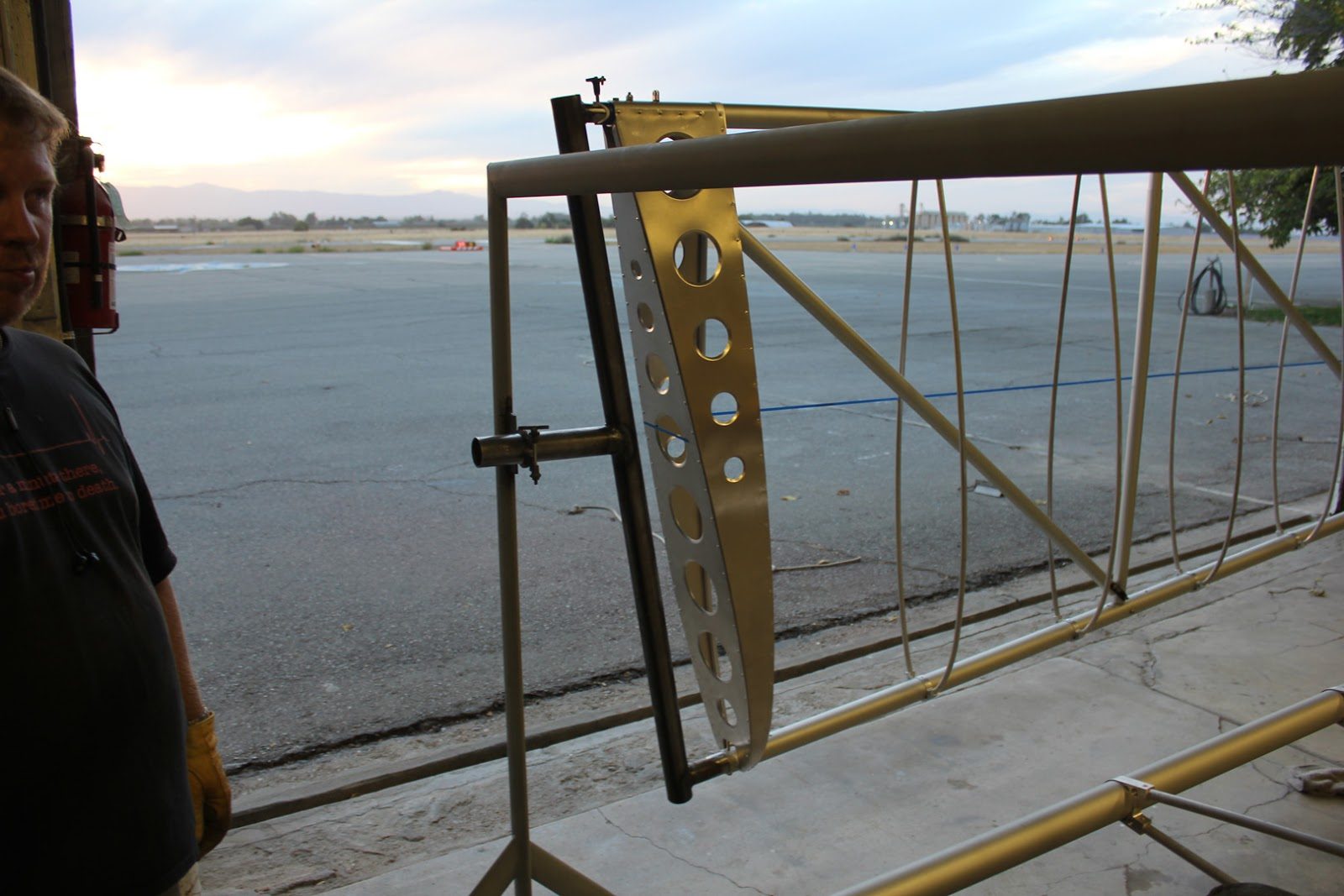
With the wing mounted onto the fixtures the act sole sticking out provides enough clearance so that we can rotate the wing 360°.
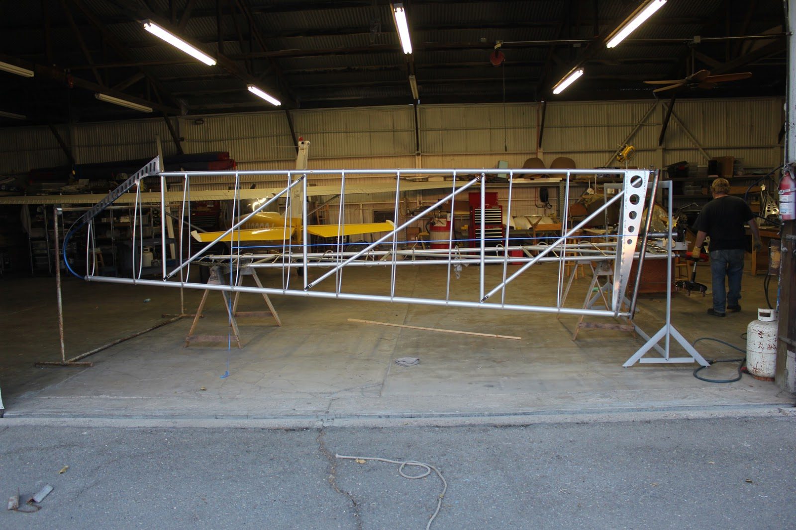
A view of both fixtures and the wing in position.
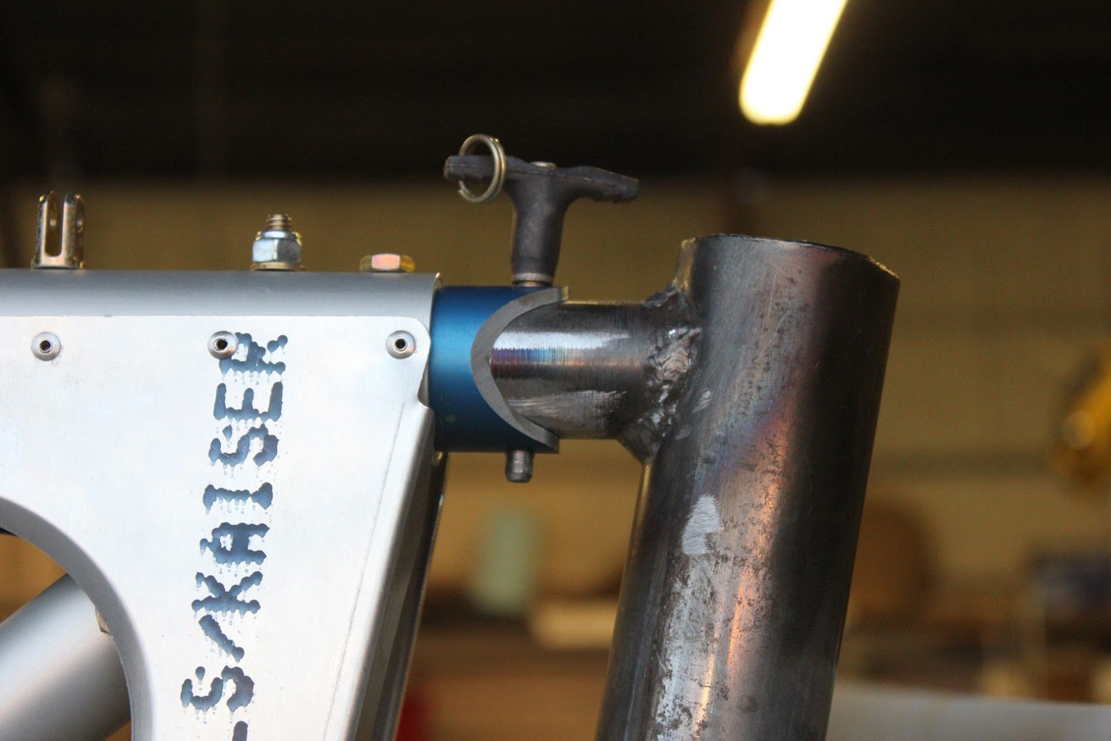
We used Quick release pins on all the fittings to be able to easily remove the fixtures from the wings.
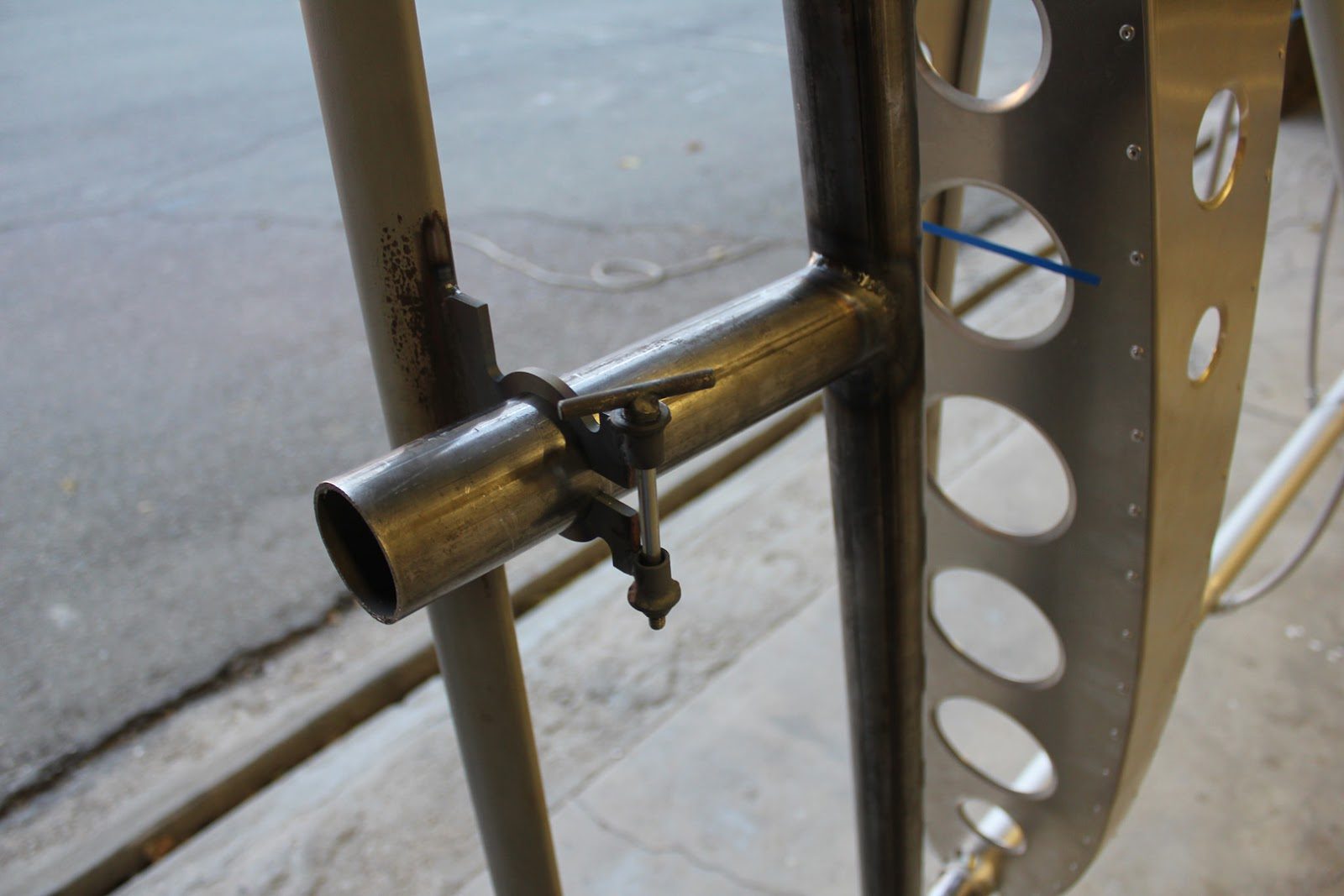
A homemade tea bolt provides tension adjustment on the axle. To give just the right amount of holding power while rotating the entire wing.
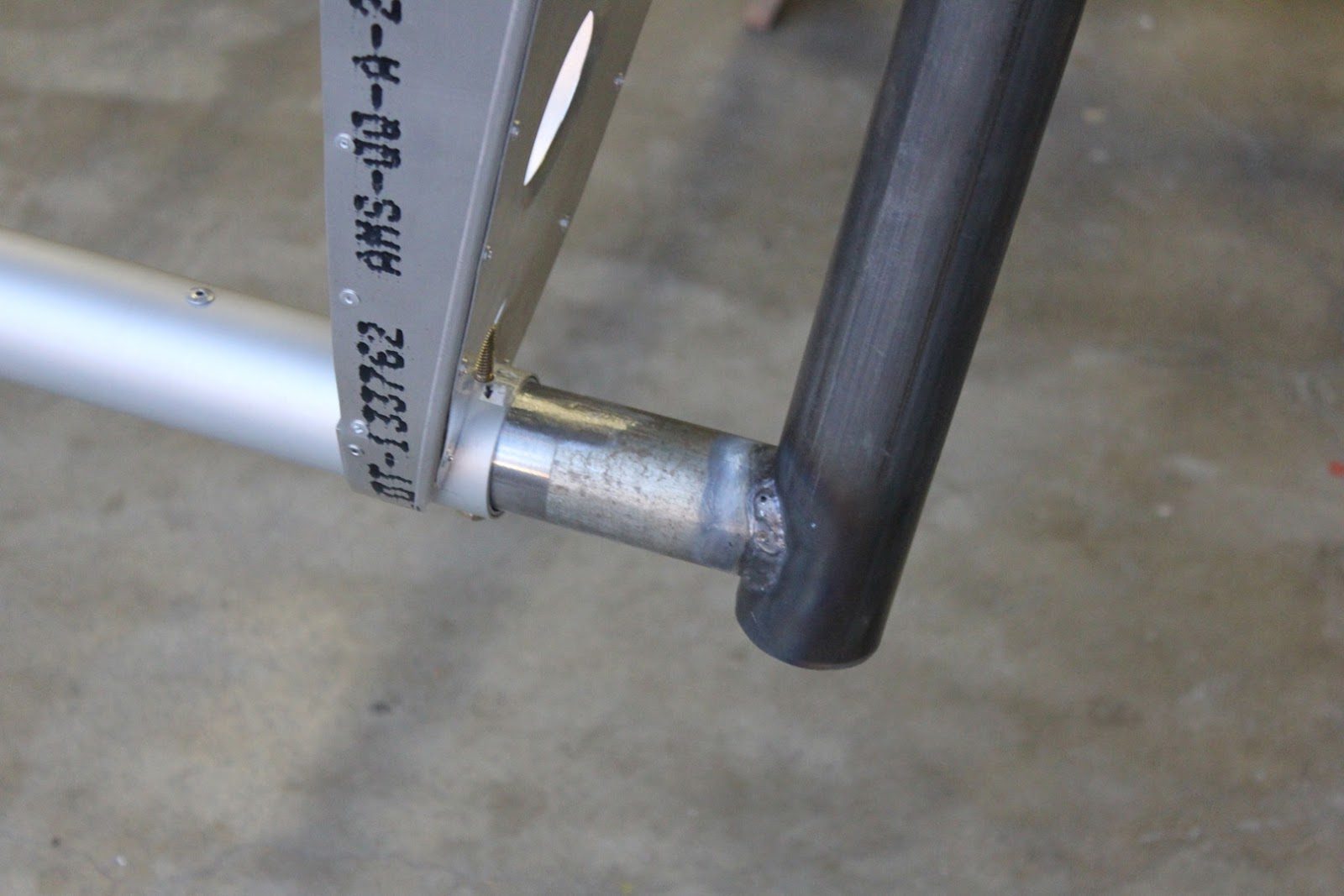
Forward spar fitting.
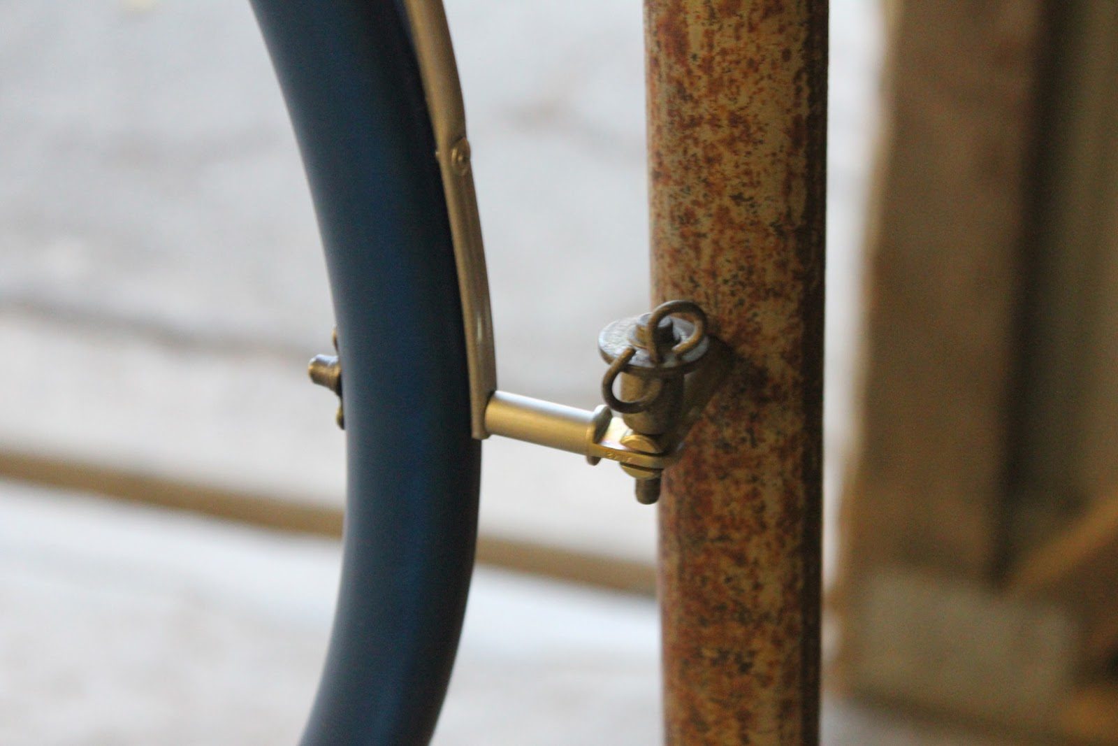
A couple of eyebolts provides for a rotating Pivoting action, allowing the wing to rotate.
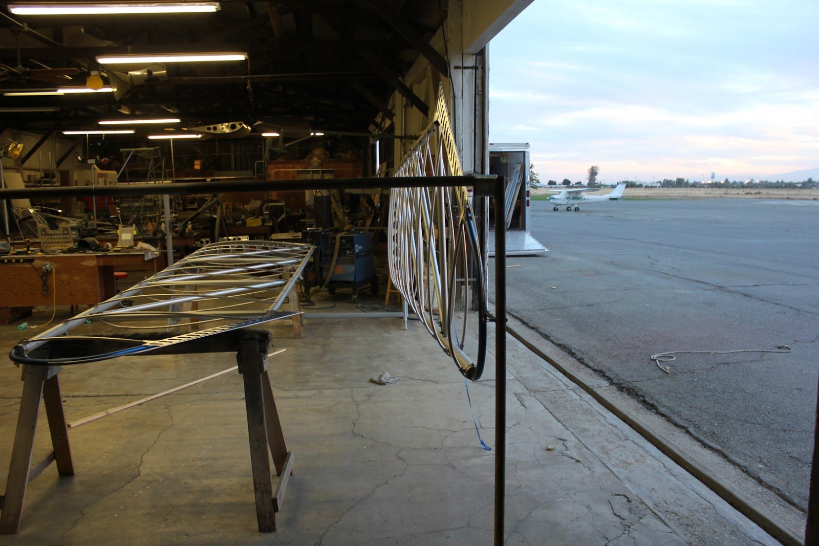
An end view
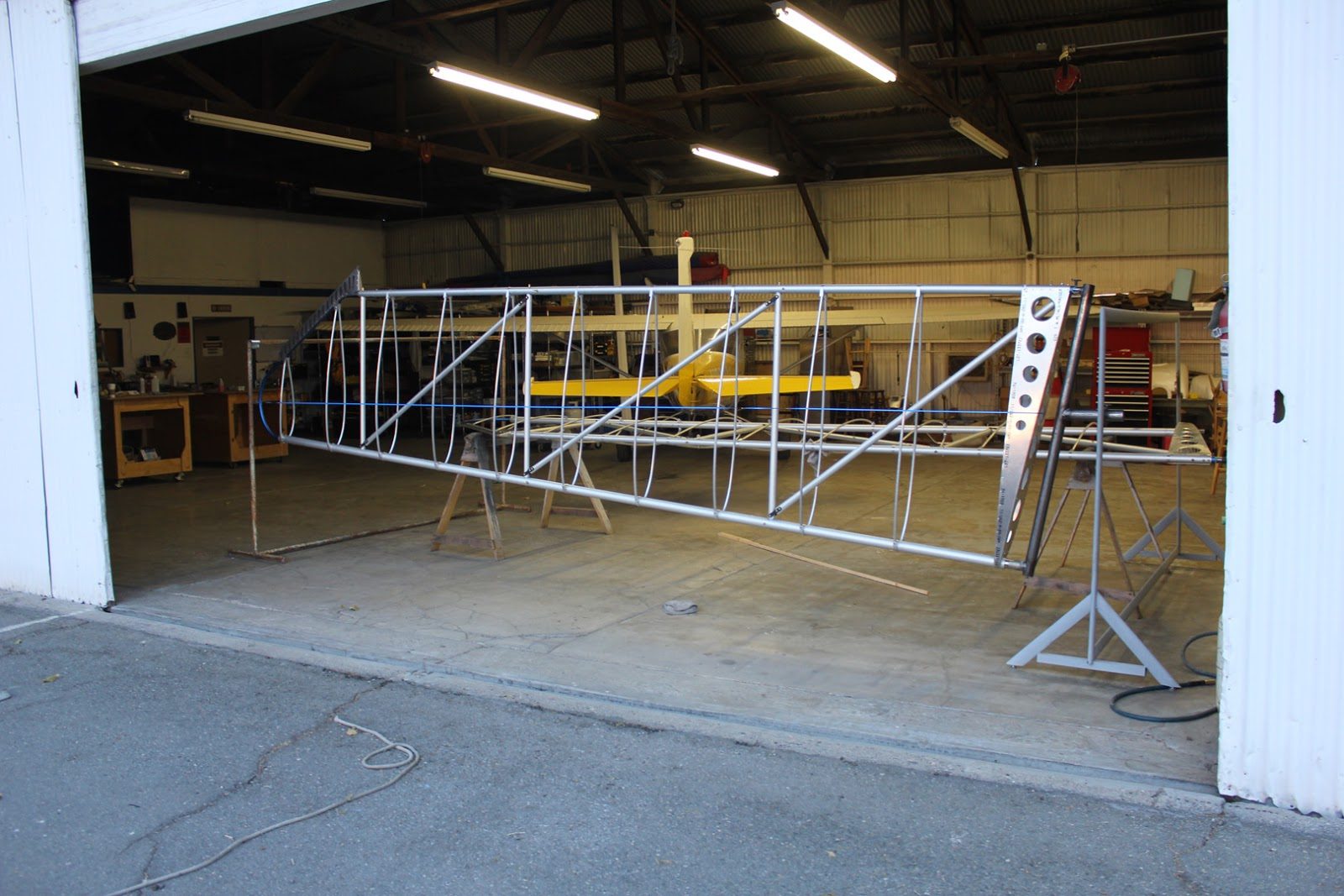
With the second wing on the sawhorses we will soon have both wings on to the fabric covering fixtures and we can begin the process of prepping for covering.
September 20, 2015 Making the Wing Holding Jigs for Covering the Wings with Fabric
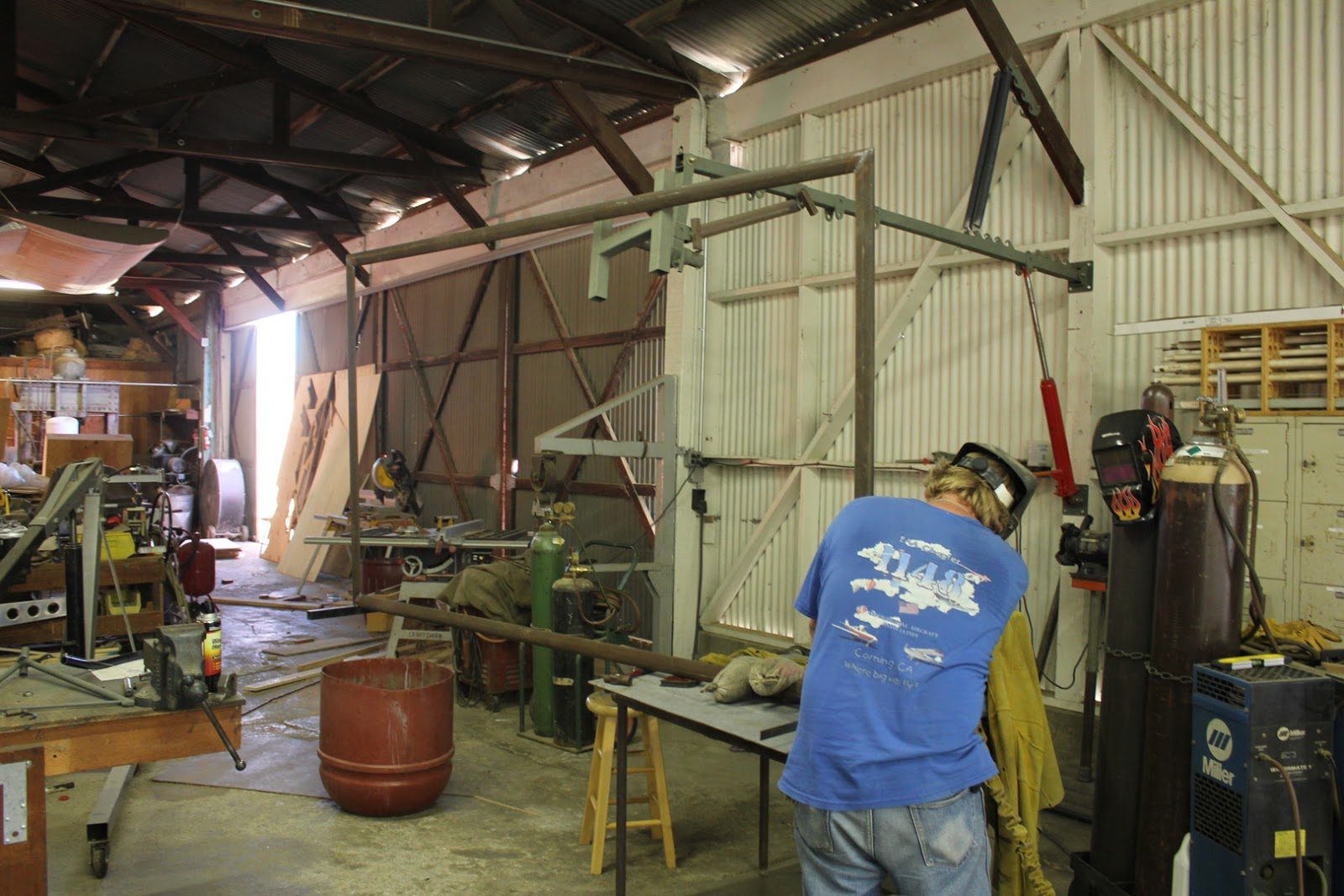
This week we are working on making up the fixtures that will be used to hold the wings in place during the covering process.
These fixtures will allow us to attach both left and right wings to these frames and rotate them 180° while we are working on them.
This will also be used as painting fixtures which will allow us to paint the entire wing with one coat having no overlaps and making it easy to spray both sides simultaneously.
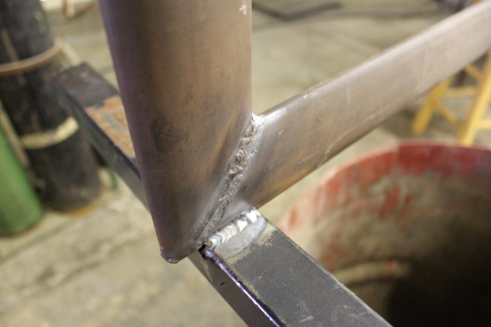
The stands are being made out of scrap material that we have in the shop. I’m not sure if you can call 12$ a foot streamlined chrome Molly steel scrap material. But nonetheless it’s been in the shop for twenty years we might as well use it
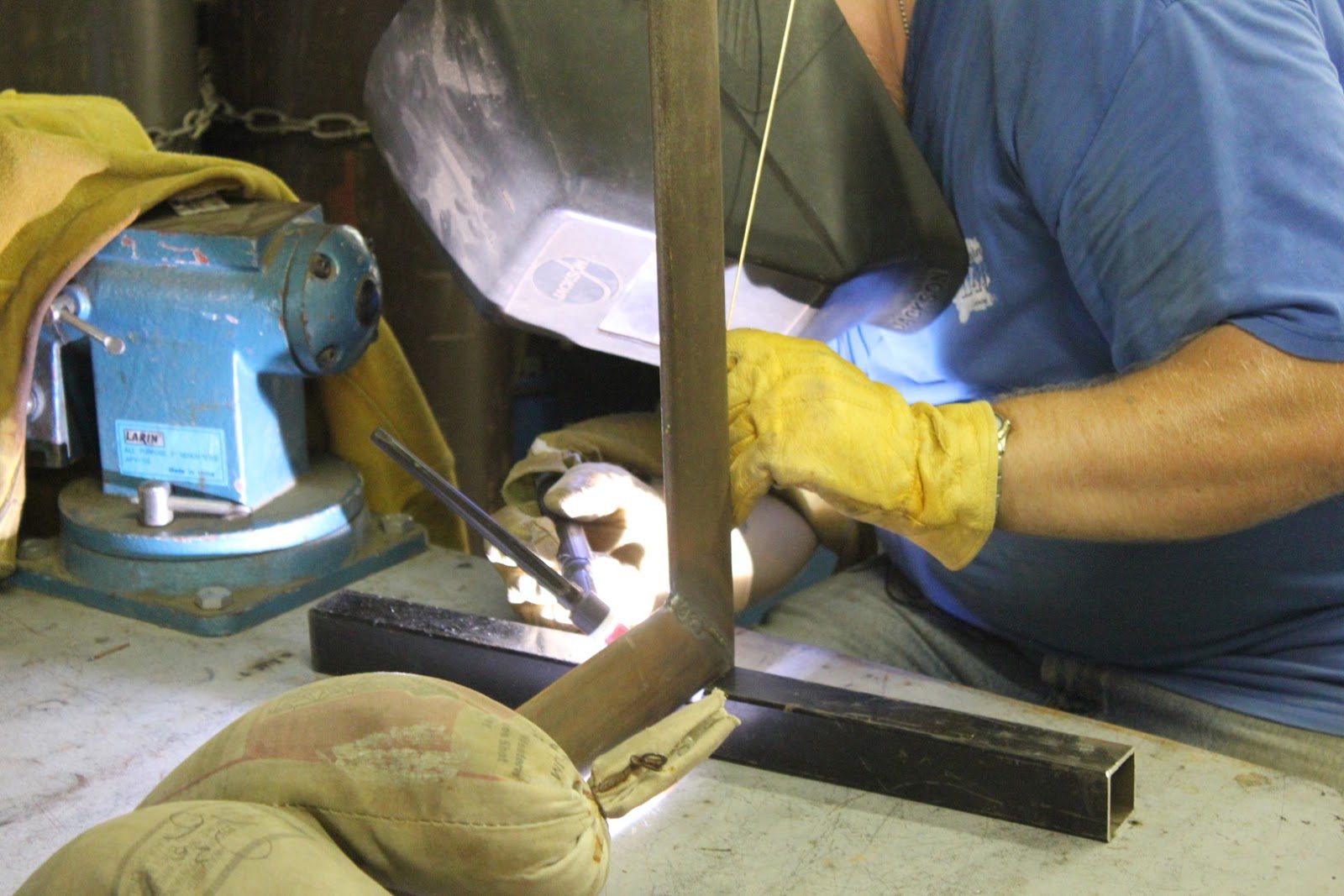
This is a good opportunity for Jason to be able to practice his take welding skills.
Any practice at all is very valuable when it comes to developing technique.
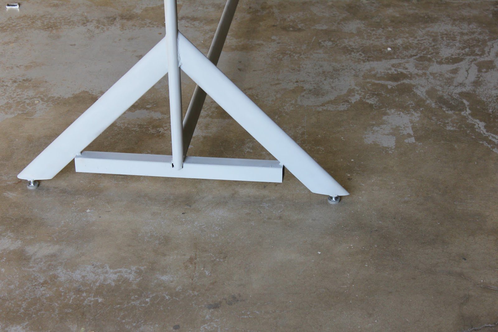
We also had some spare adjustable feet that we installed on the new fixture to go along with the other fixture. This will allow us for precision leveling.
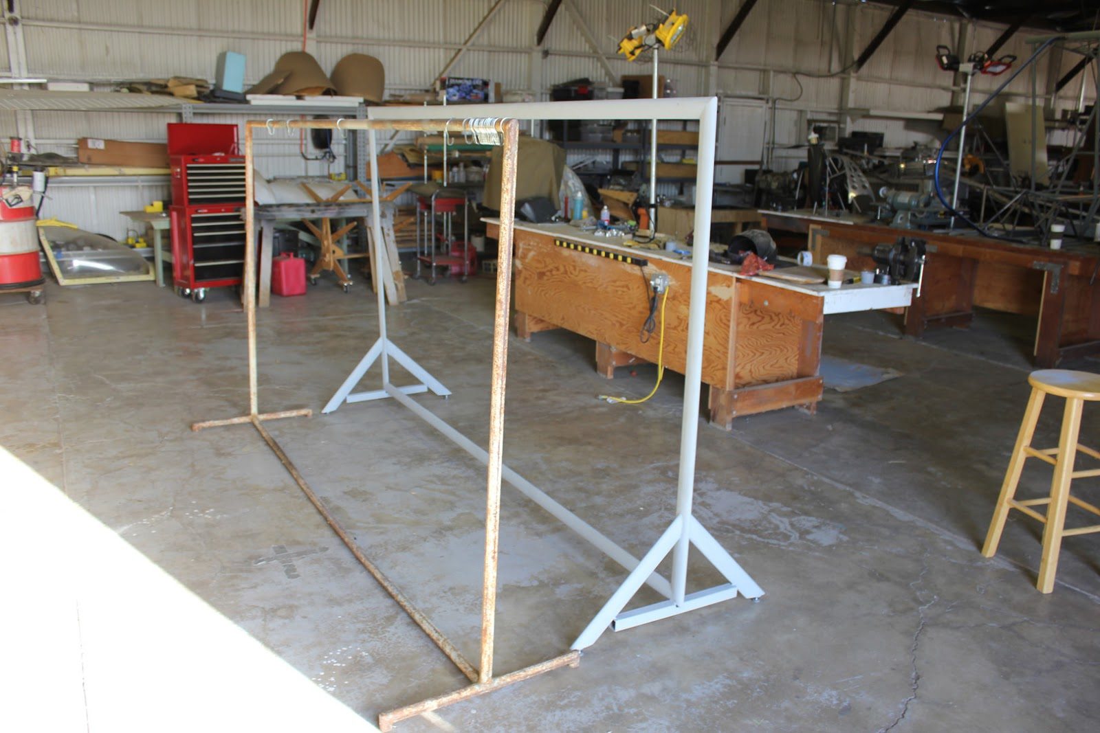
The stand on the left will be used for holding the wing tip and the stand on the right will be used for holding the wing root.
We still need to manufacture additional fittings to adapt to the wings.
September 19, 2015 Machine Shop Making Parts
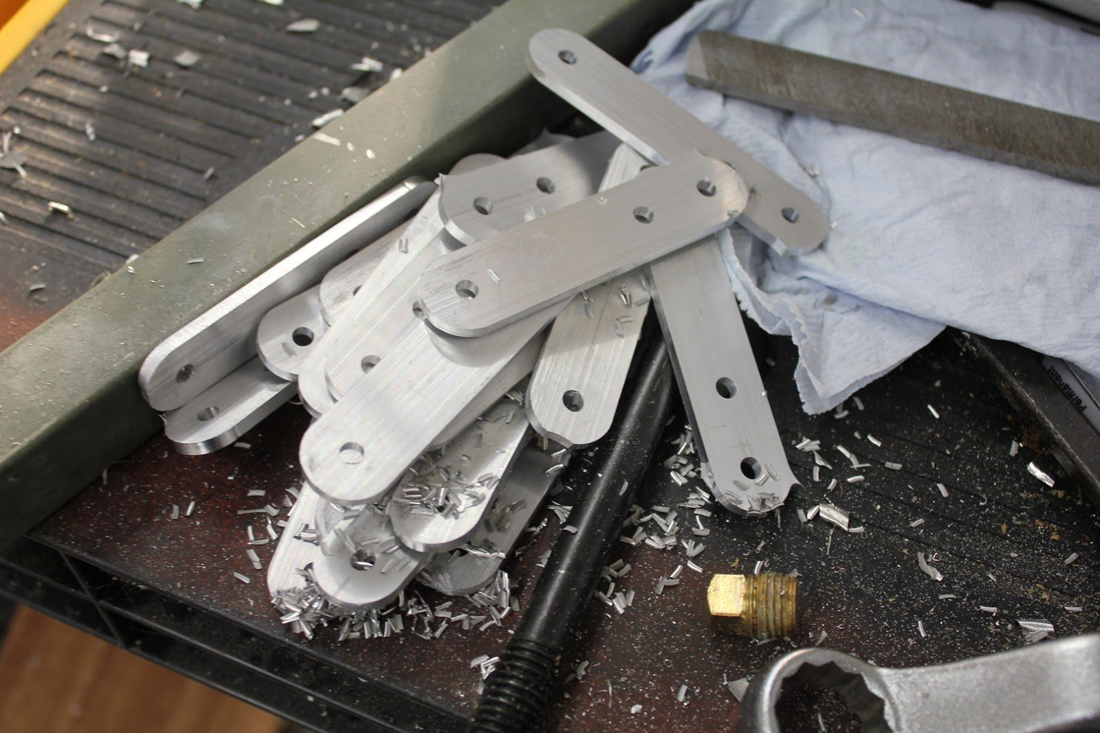
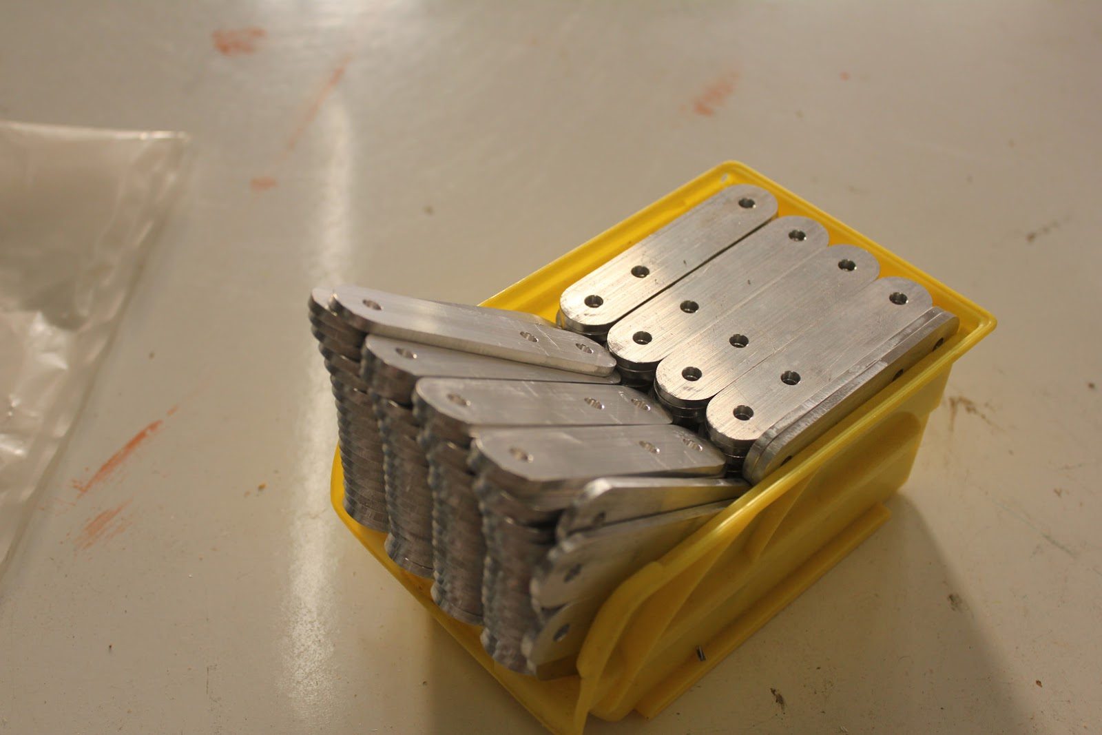
Almost every day, the CNC machines in the machine shop are busy producing parts.
These are the fittings that are used to connect the wing drag/anti-drag struts to the main wing compression struts.
September 15, 2015 Reno Air Races
September 14, 2015 EMG-6-250 Fun Flying September 2015 (Video)
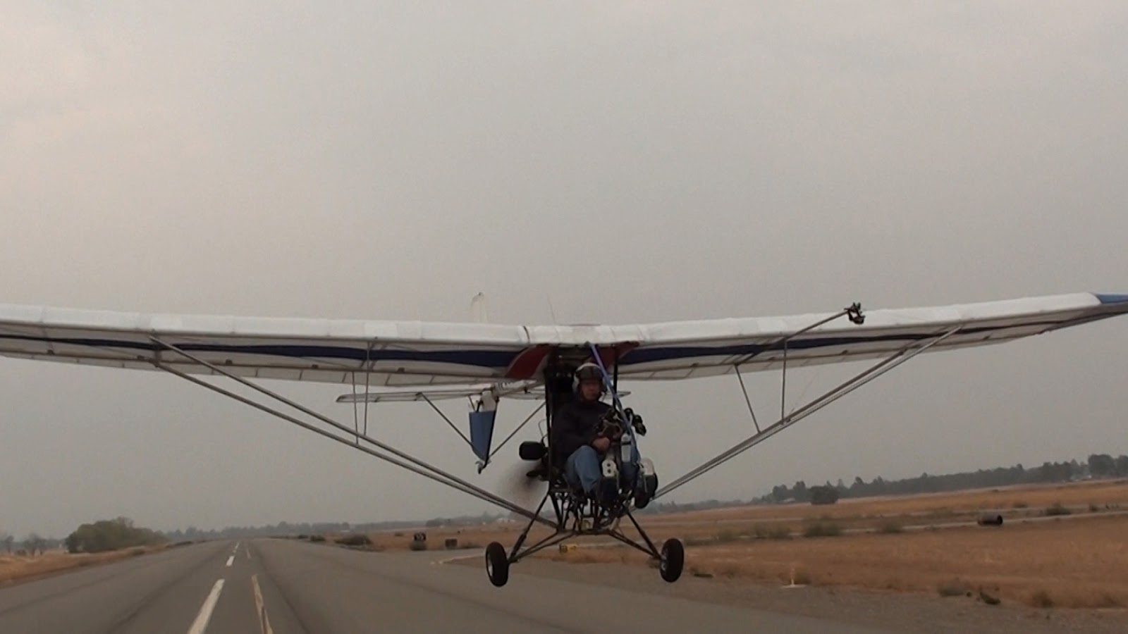
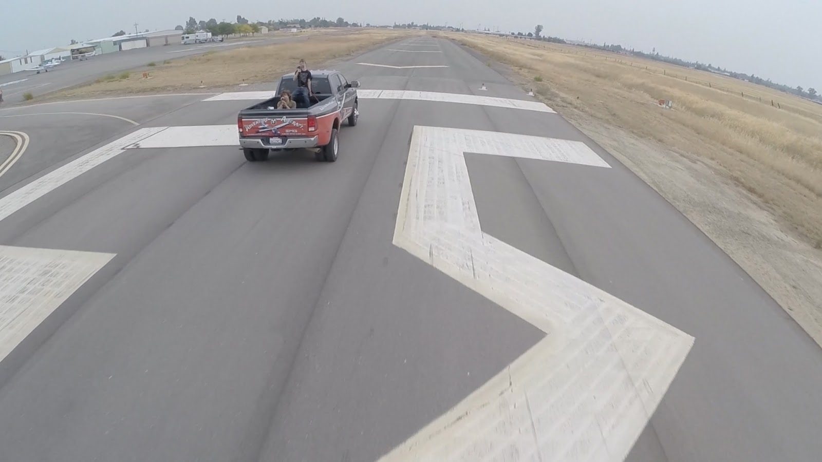
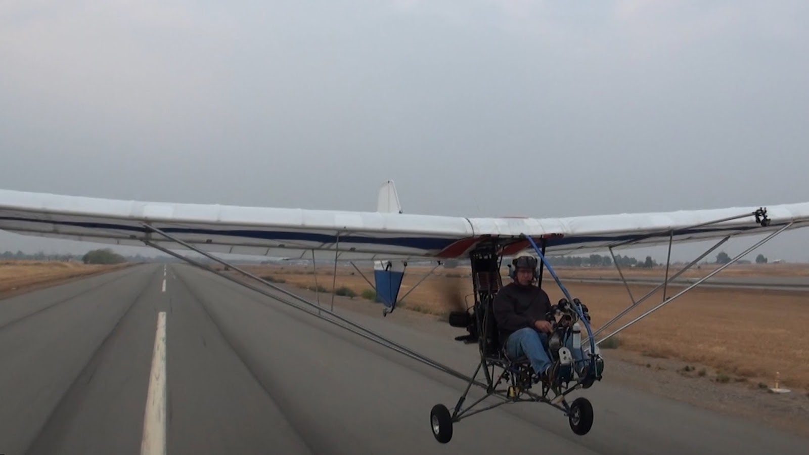
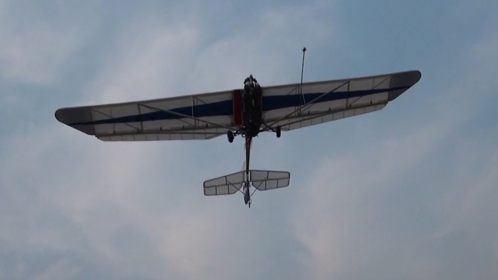
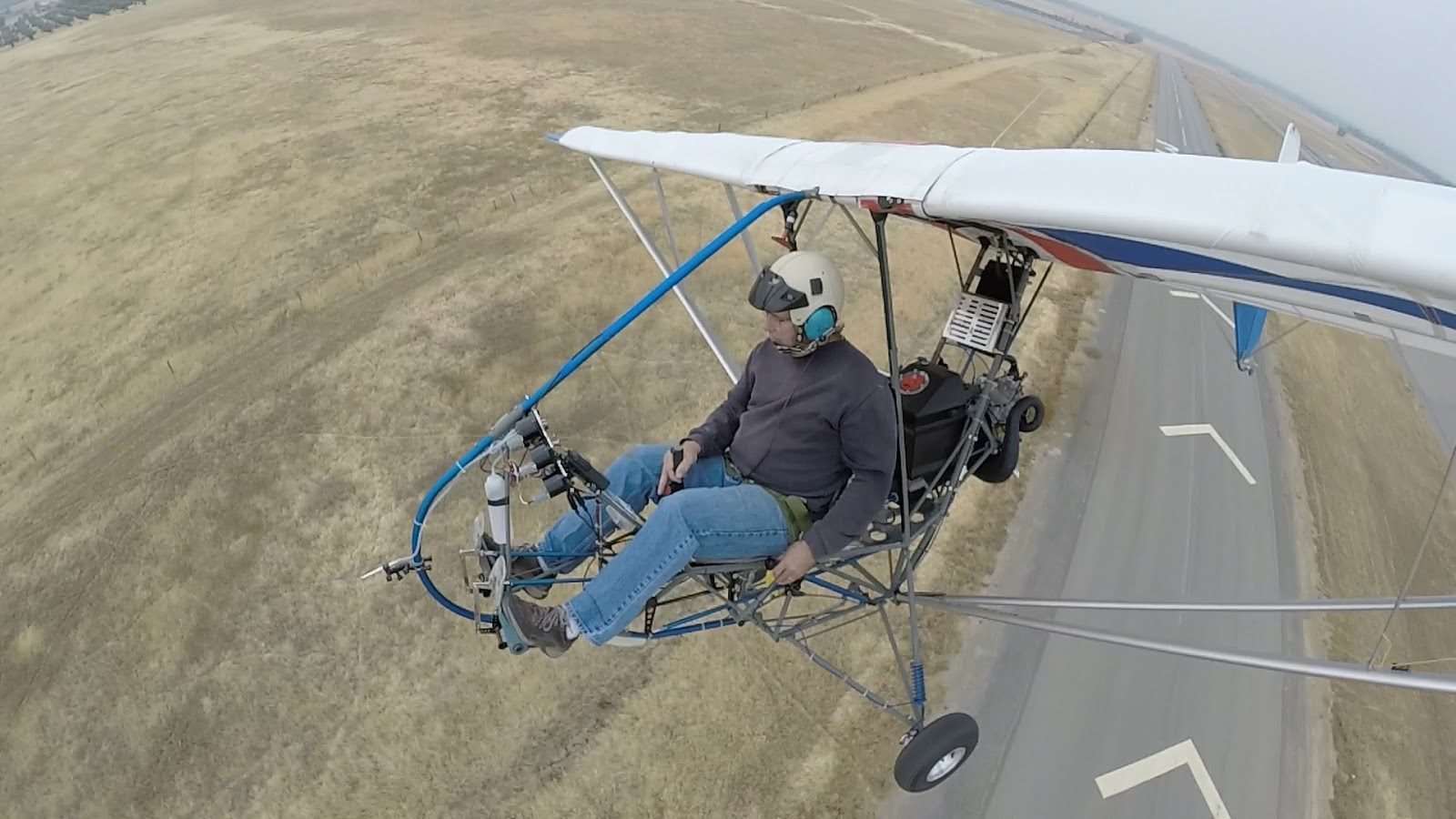
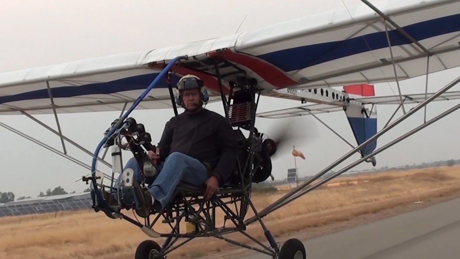
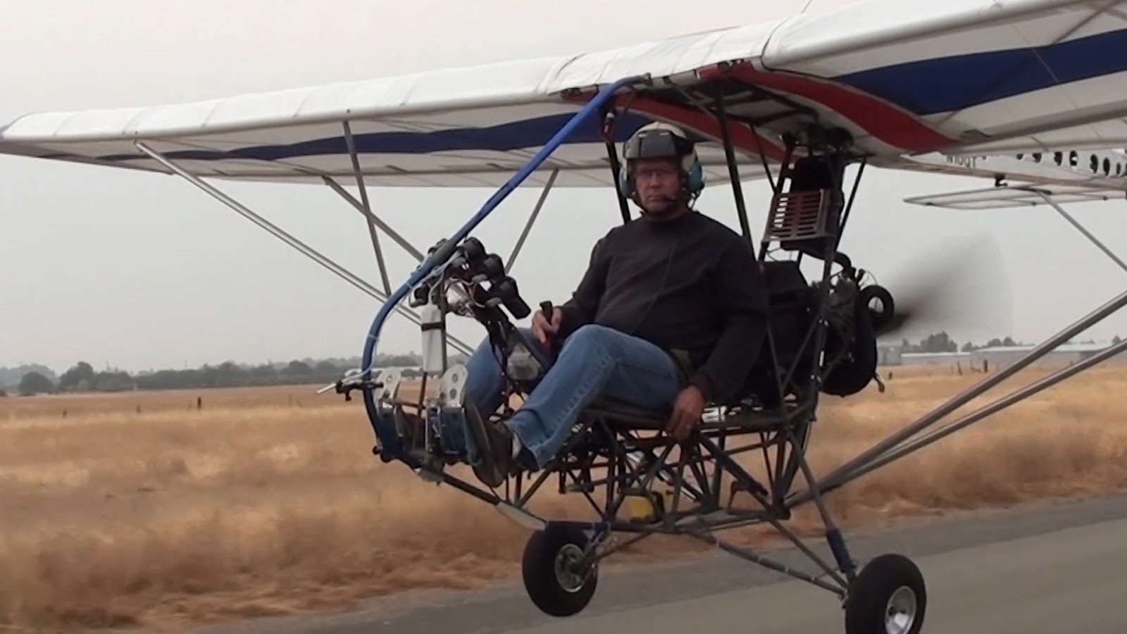
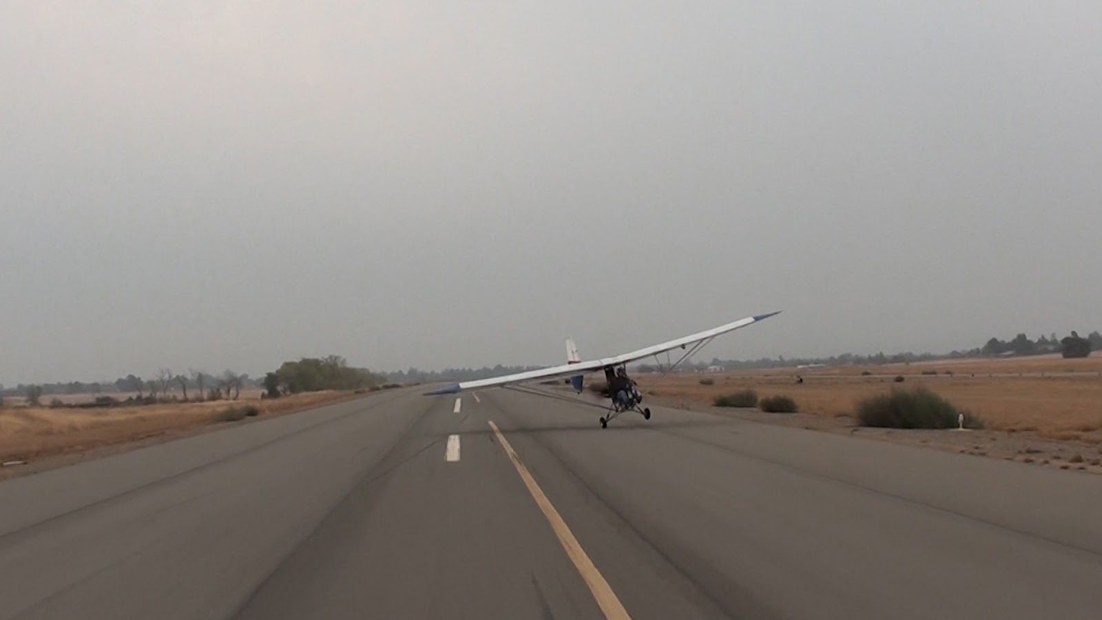
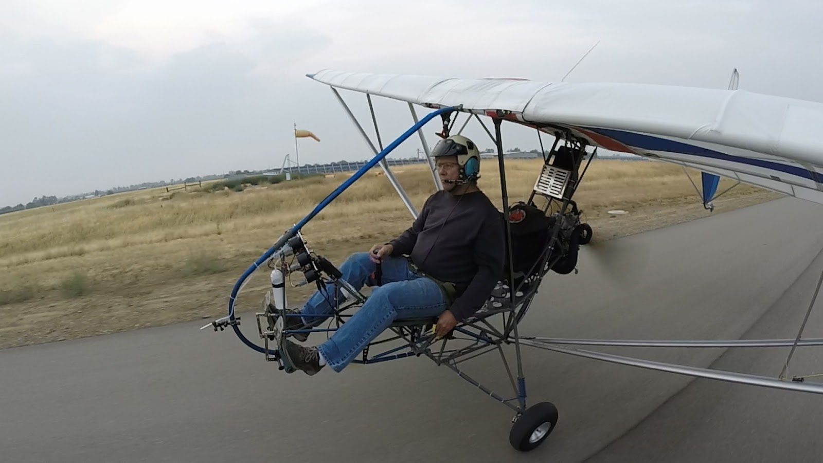
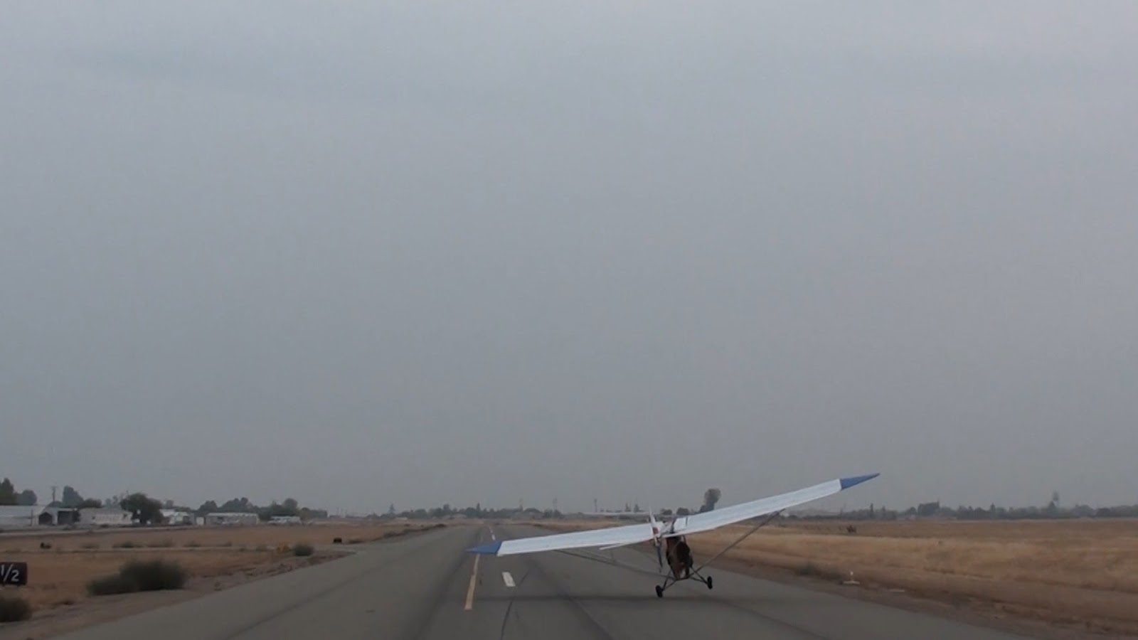
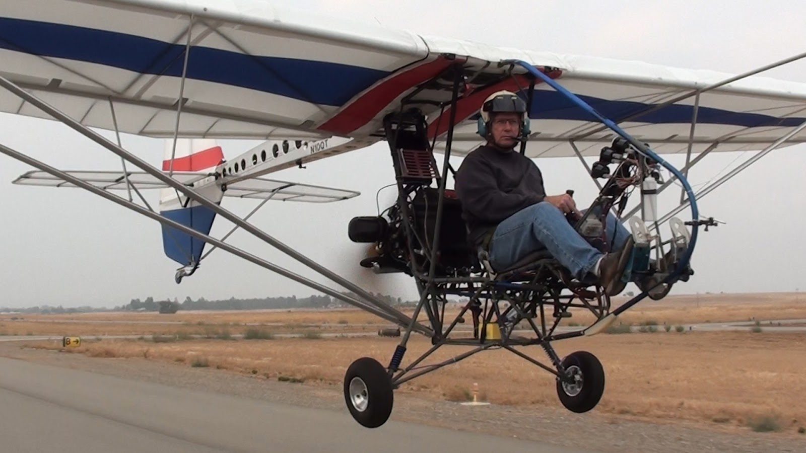
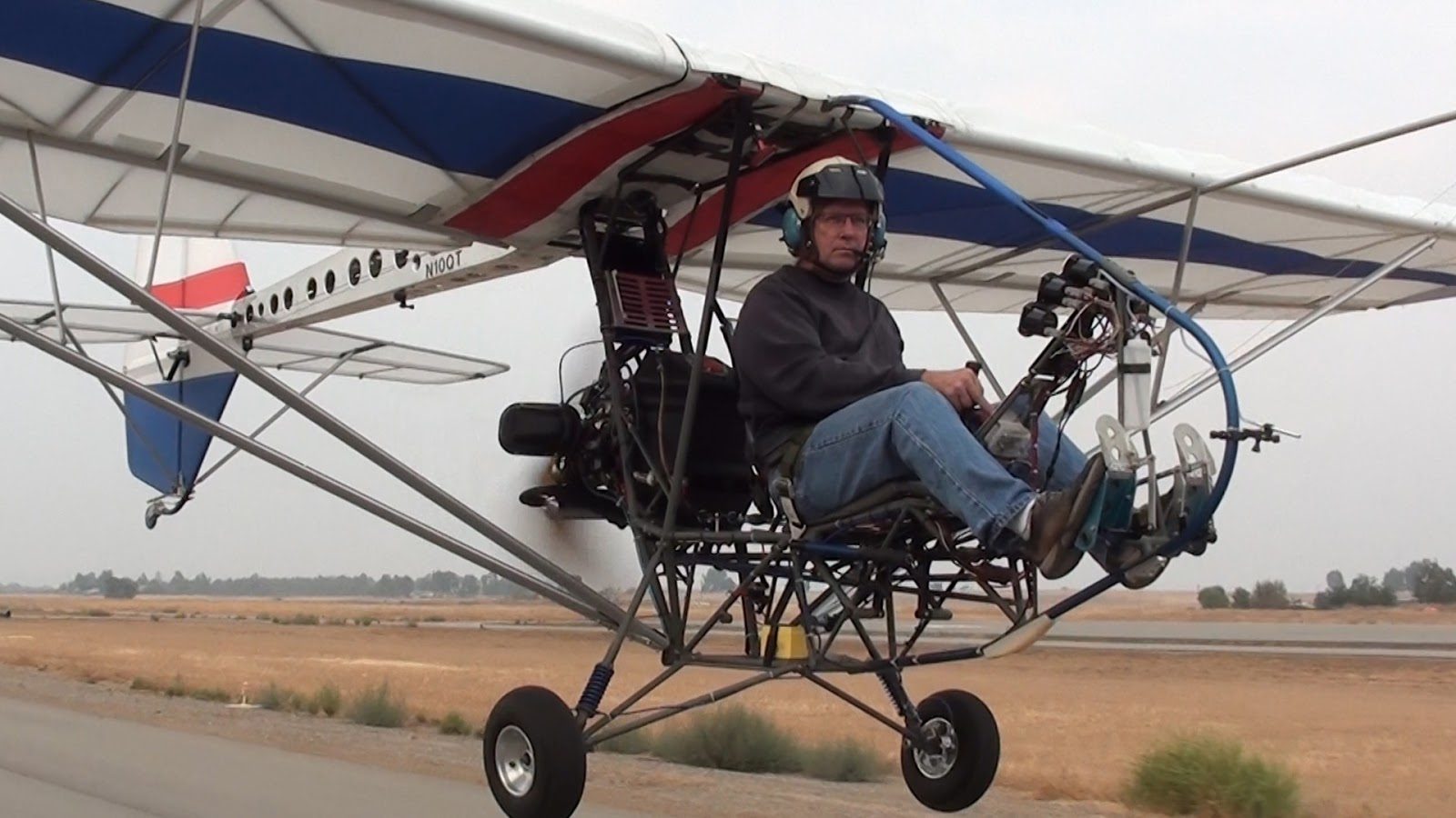
September 13, 2015 EMG-6-250 Back in the Air For the first time since the Oshkosh Airshow.
We finally had an opportunity to put the EMG-6 back together after having the airplane disassembled for the trip to and from Oshkosh.
We took the opportunity to conduct the test flight and get some video taken at the same time.
The video should be posted in the next couple of days on the YouTube channel.
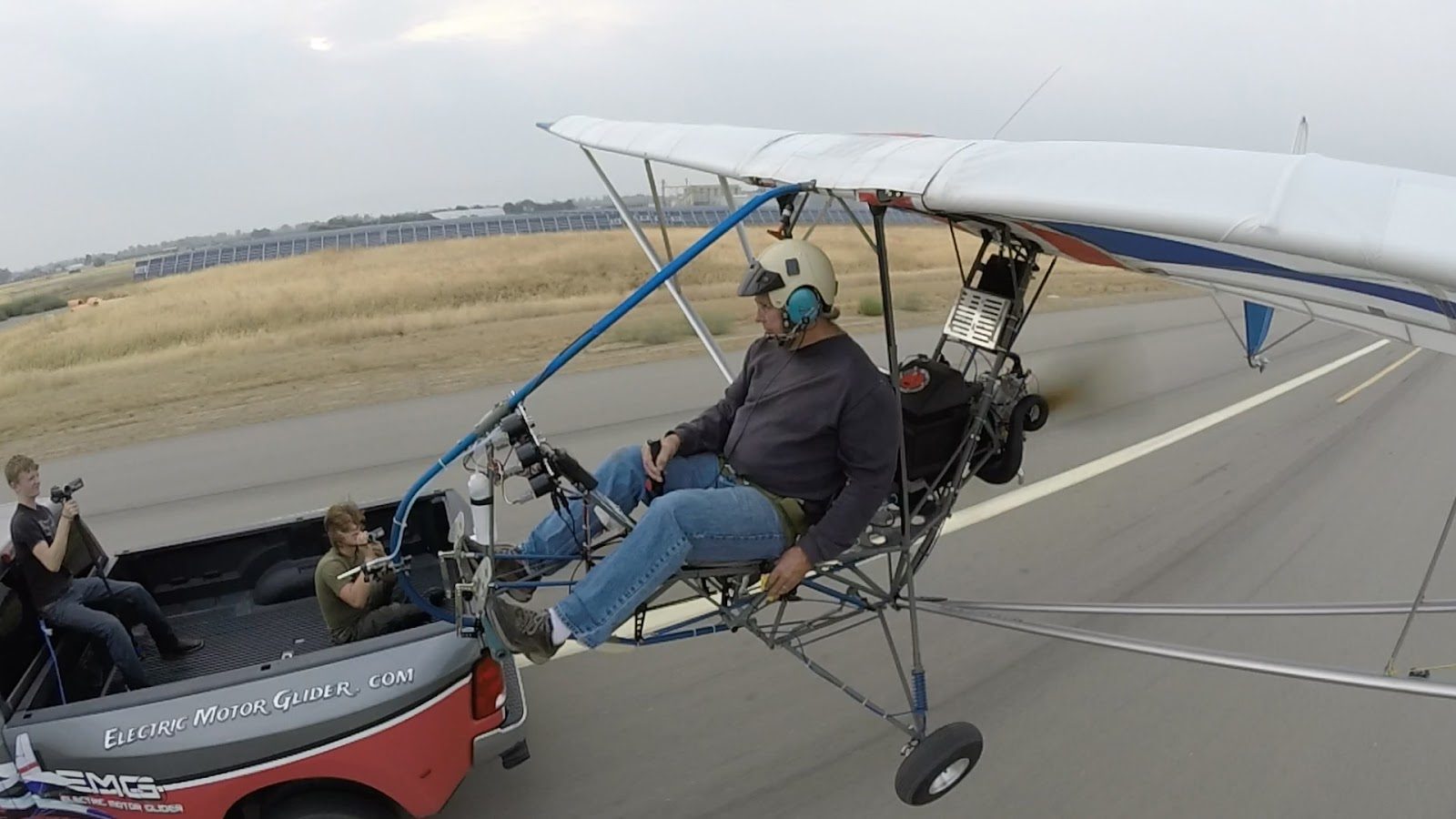
If you click on the pictures below, they will turn into a full-size picture with a slideshow format.
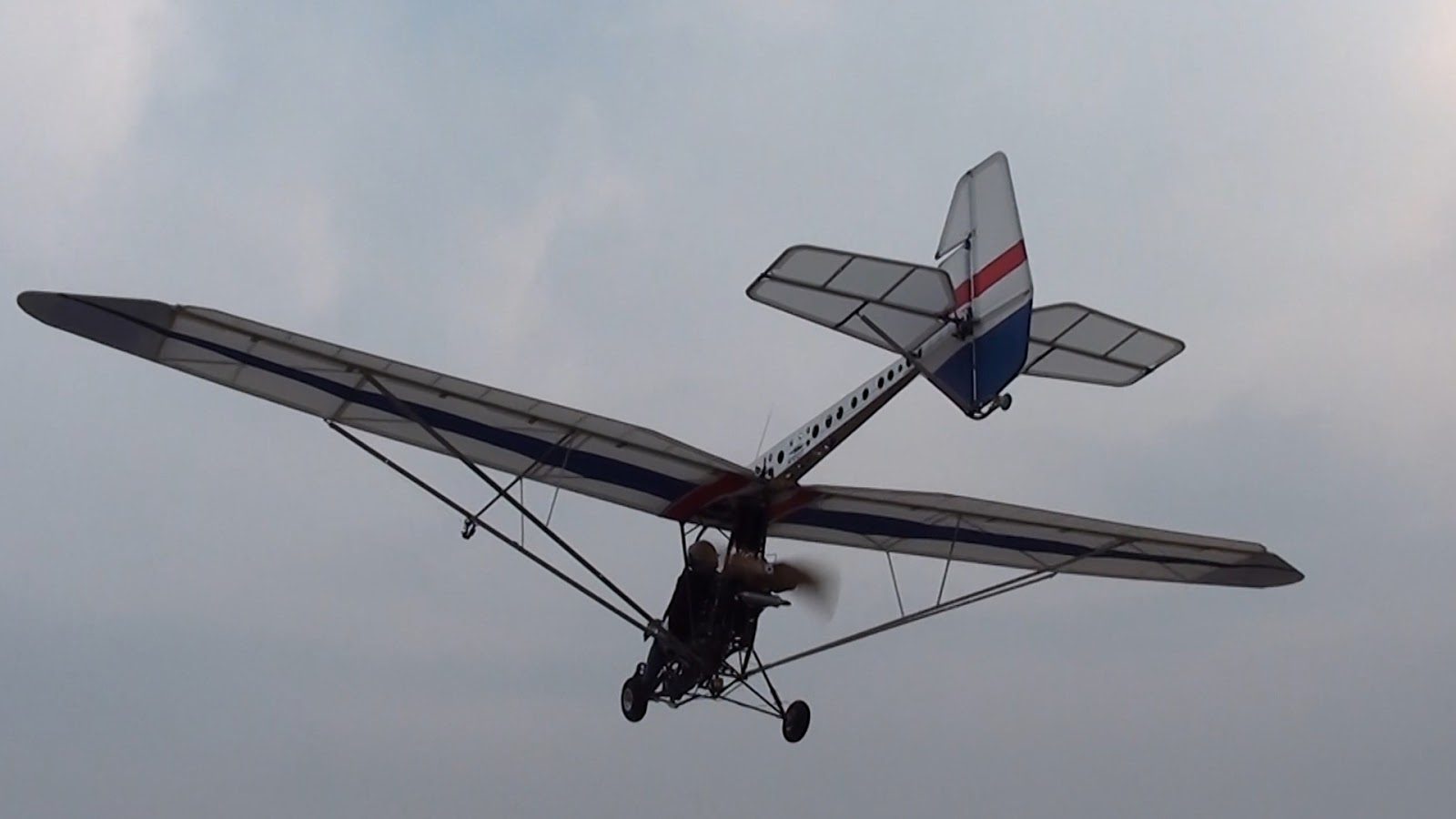
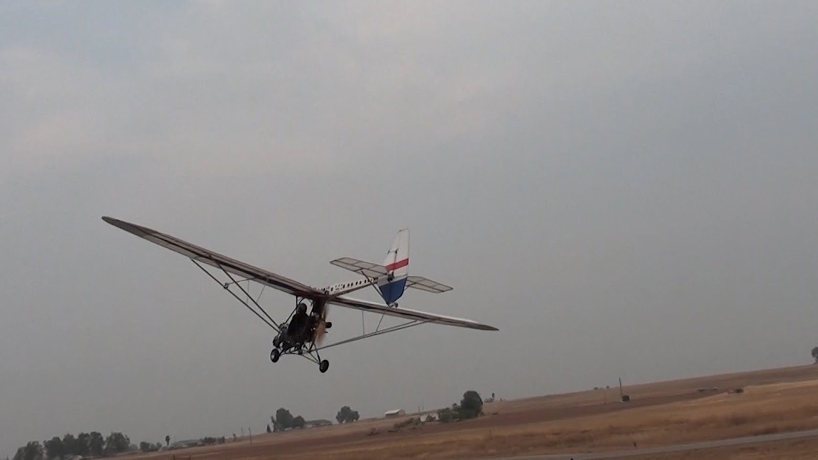
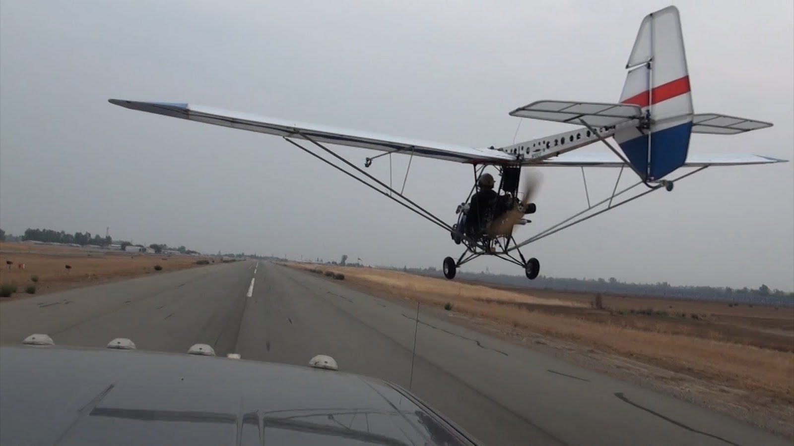
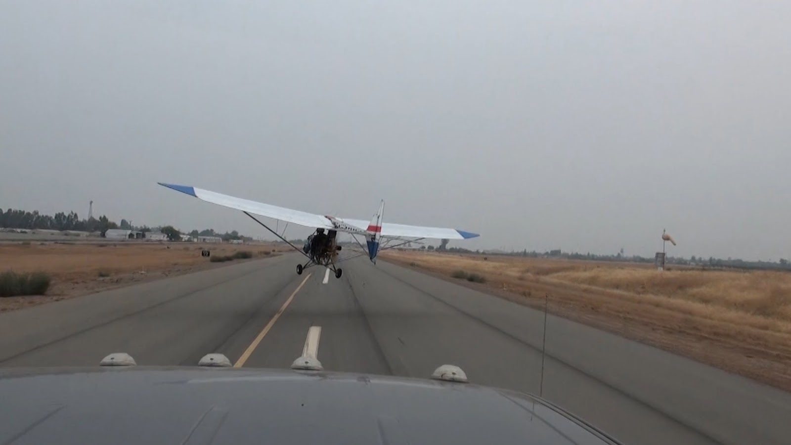
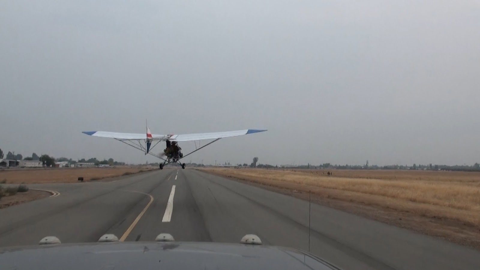
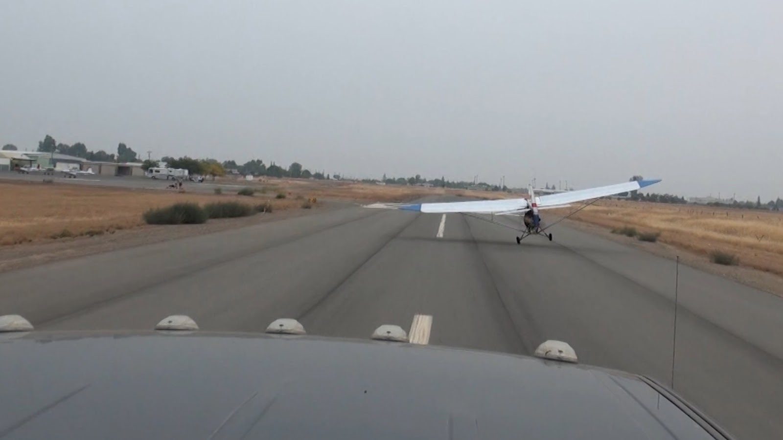
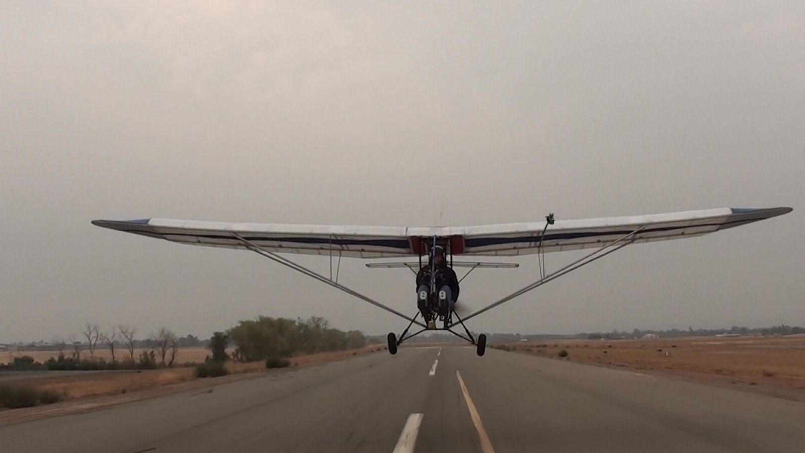
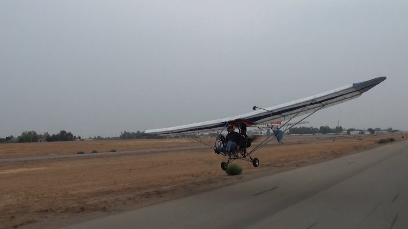

September 11, 2015 New Video “Manufacturing the Wing Rib Attach Fittings”
September 10, 2015 New Video ” Manufacturing Wing Ribs”
September 9, 2015 Manufacturing of wing ribs
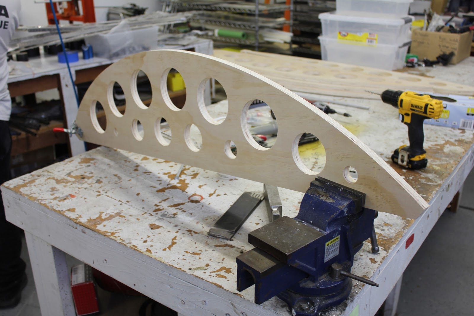
We have completed the CNC cutting of the wing rib bending fixtures.
In this picture here we have the lower wing rib profile bending jig ready to be used.
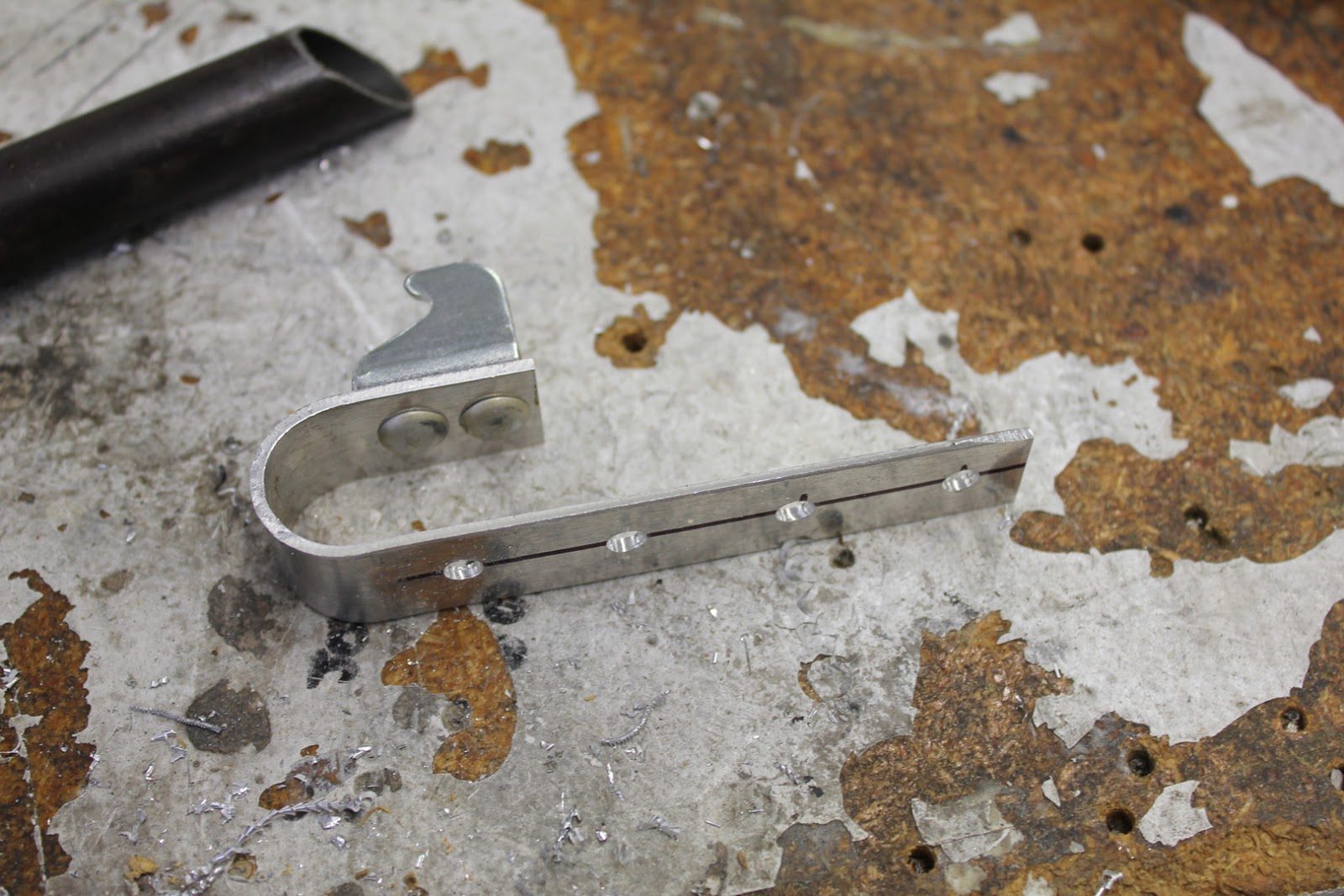
Before we could use the bending fixtures we had to make up a holding fixture for the tubing which secures the tube at the nose of the bending jig during the bending process.
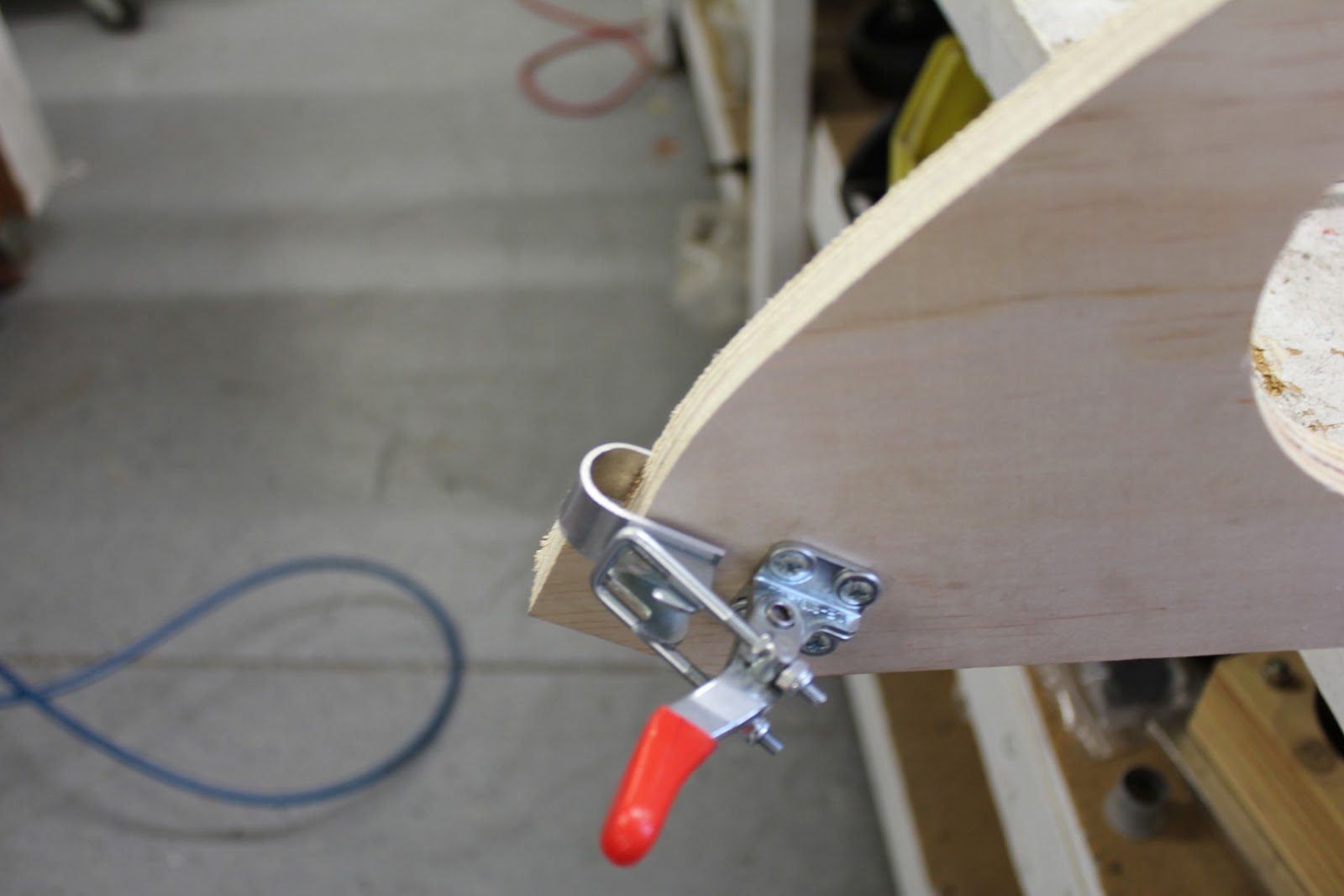
We manufactured a U-clip which could be secured to the bending fixture and then using an adjustable toggle clamp apply just enough pressure to hold the tube during the bending process
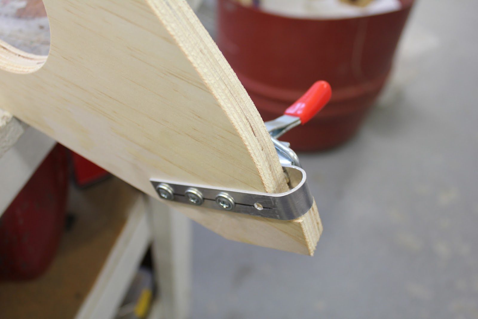
The reverse side of the lower rib bending fixture.
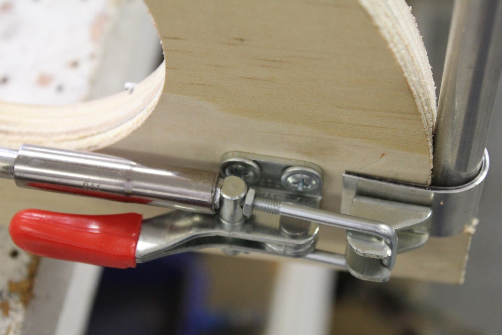
In this picture here we can see the socket being used to adjust the tension on the toggle clamp.
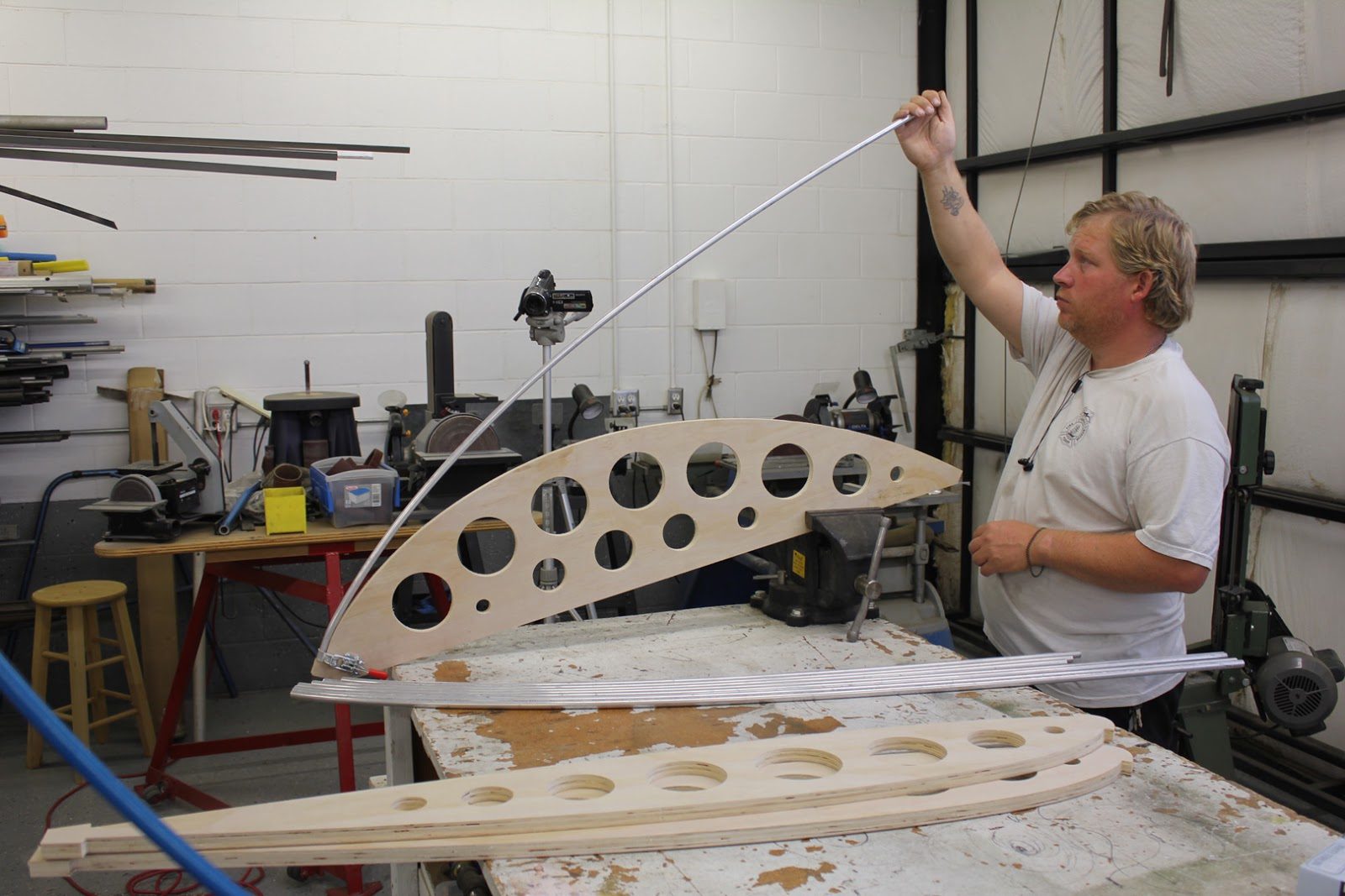
The next sequence of photos shows positioning the stock aluminum tube into the bending fixture of the lower wing rib bending jig and pulling smoothly down along the profile until the rib is bent to the proper contour.
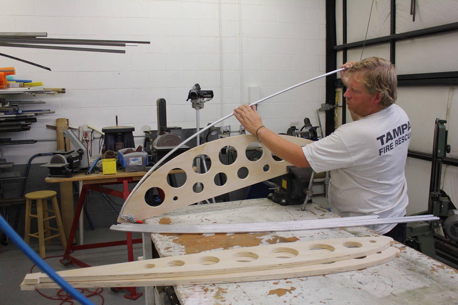
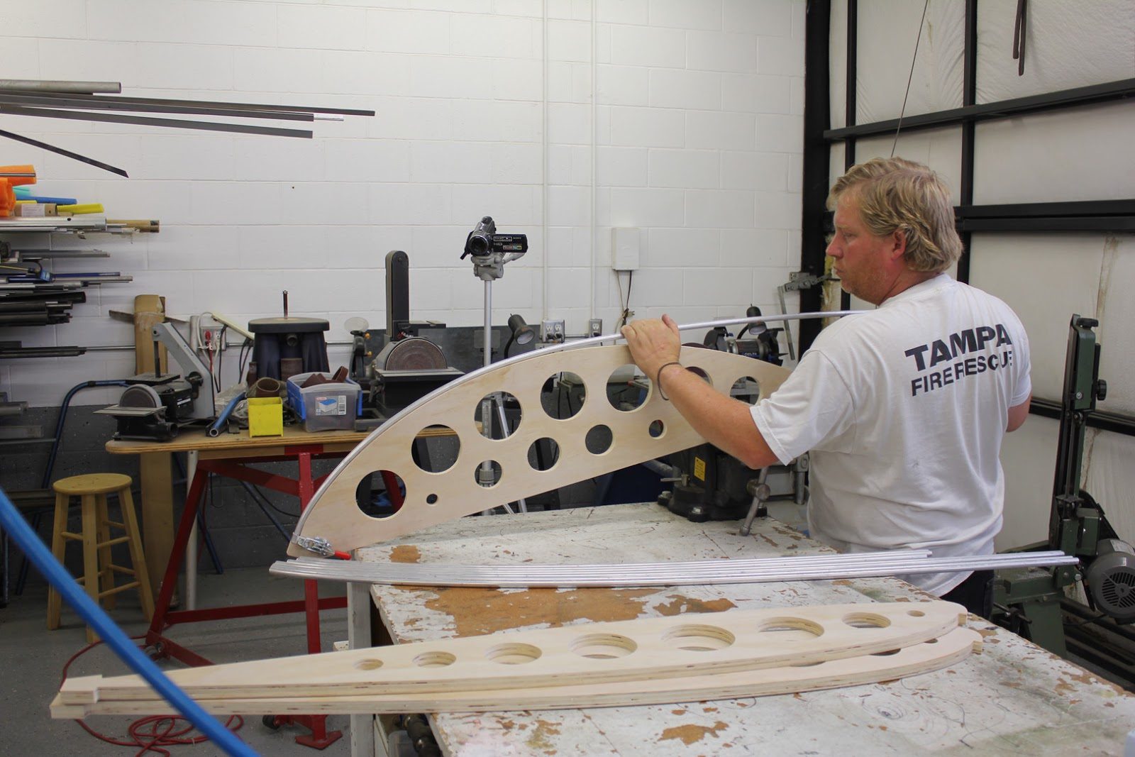
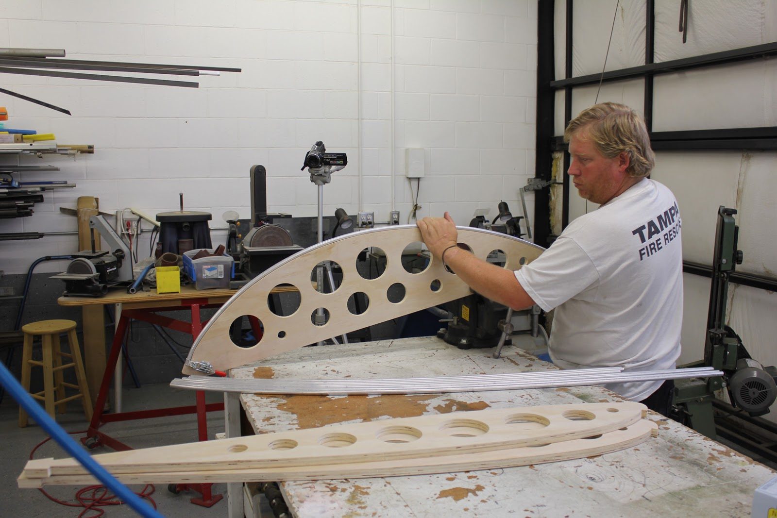
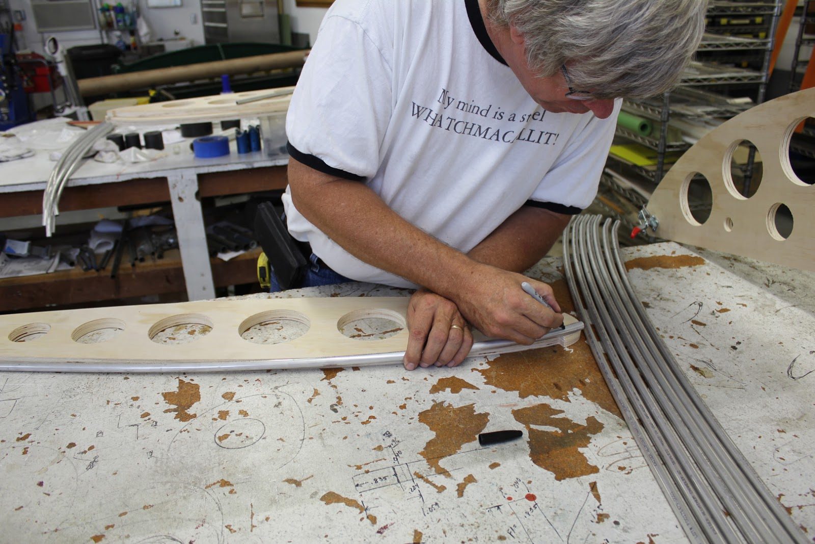
Once the ribs have been bent they are positioned on to the profile template and marked for the cutting of the leading edge section so that the rib tube may properly position into the leading edge rib fitting.
In the next couple of days we should have a YouTube video on the complete process of manufacturing the ribs
September 8, 2015 Wing Rib Bending Jig’s
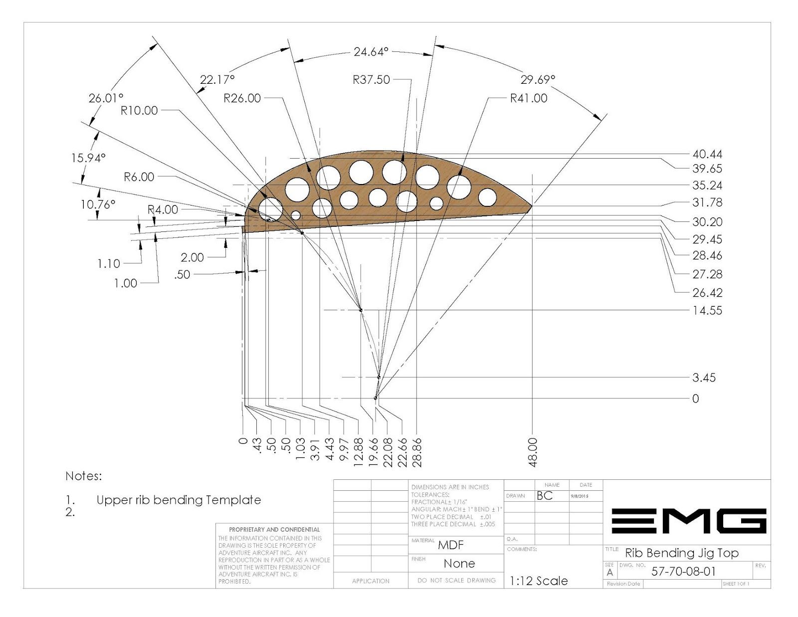
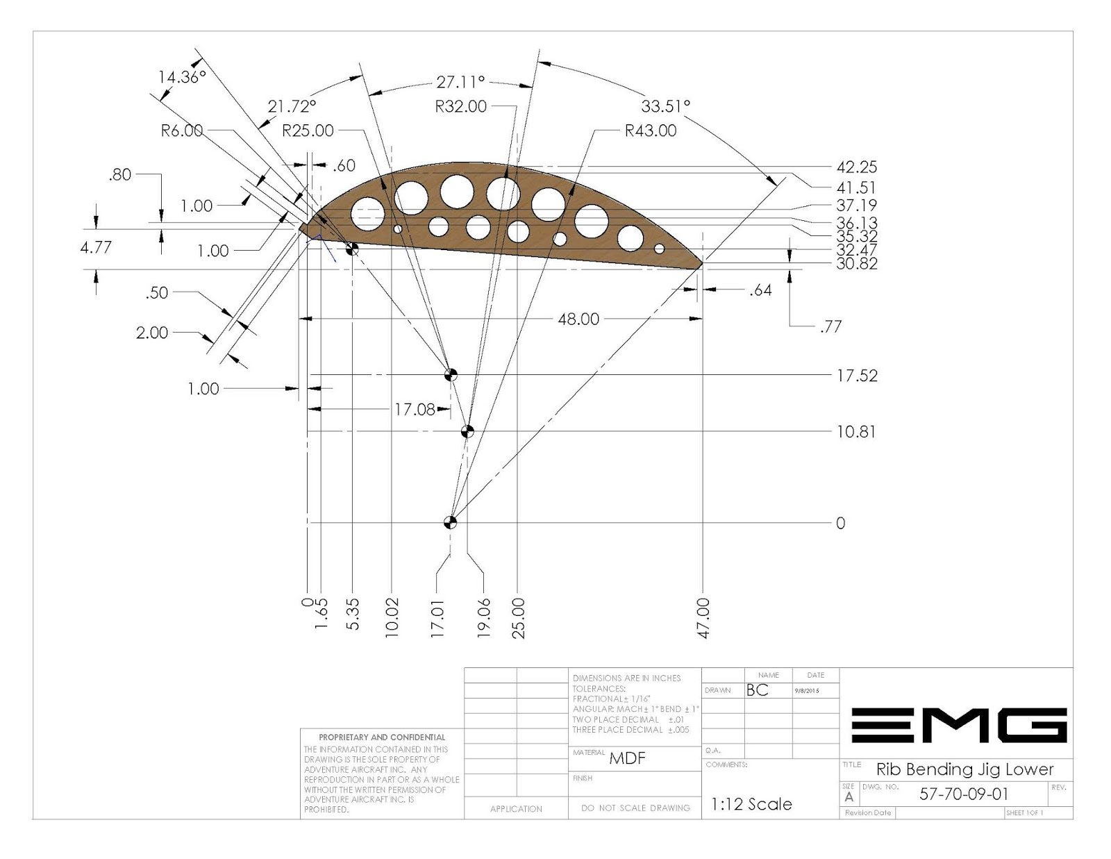
We have changed the rib mending jigs to include lightning holes and reduce the overall profile, which will lower the shipping weight and costs for those that would like to rent the rib bending jigs.
In addition to the availability of the 3 rib mending jigs. There are also on the builder database. DXF files which will allow you to send the files to your local cabinet shop and have them CNC manufactured.
In addition to that the PDF files on the drawings have enough data that it is pretty easy to lay out on a piece of MDF or plywood the dimensions and duplicate the jigs without much effort.
There is one bending jig for the upper profile rib.
And there is one bending jig for the lower profile rib.
In addition to the bending jig’s there is also a profile jig which is used for ensuring that the bent rib matches perfectly with the airfoil profile design for the airplane. This is a NACA 23015 airfoil.
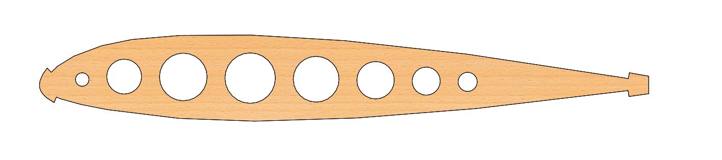
The ribs can be placed directly on to the profile and after positioning the leading edge of each rib can be marked at the cut off position for the leading edge to ensure proper positioning. Once placed on to the aircraft.
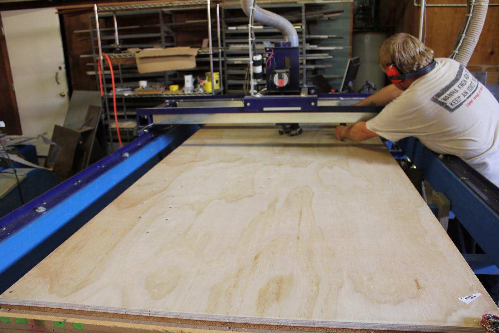
In the picture. The right we are positioning a piece of cabinet grade plywood onto the CNC router and are preparing to cut out a set of 3 rib bending jig’s.
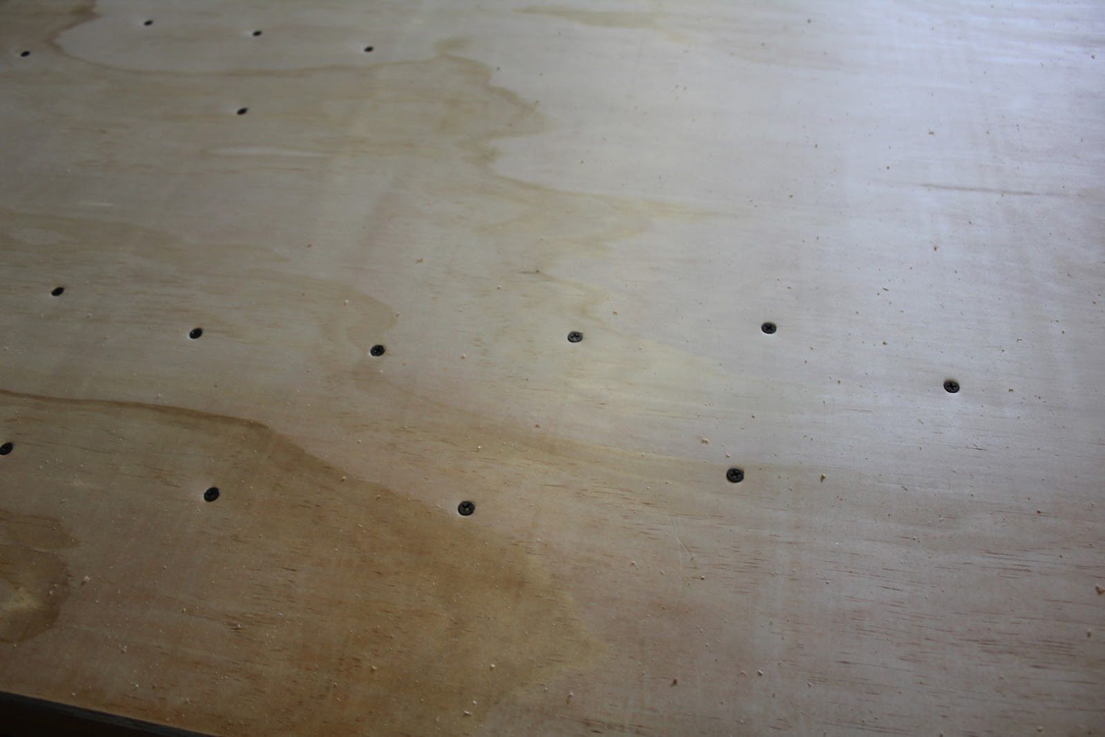
The 1st step of cutting any piece of plywood is that all of the small pieces have to be drilled and screwed in place so that they do not pop up during the cutting process and jam the CNC router.
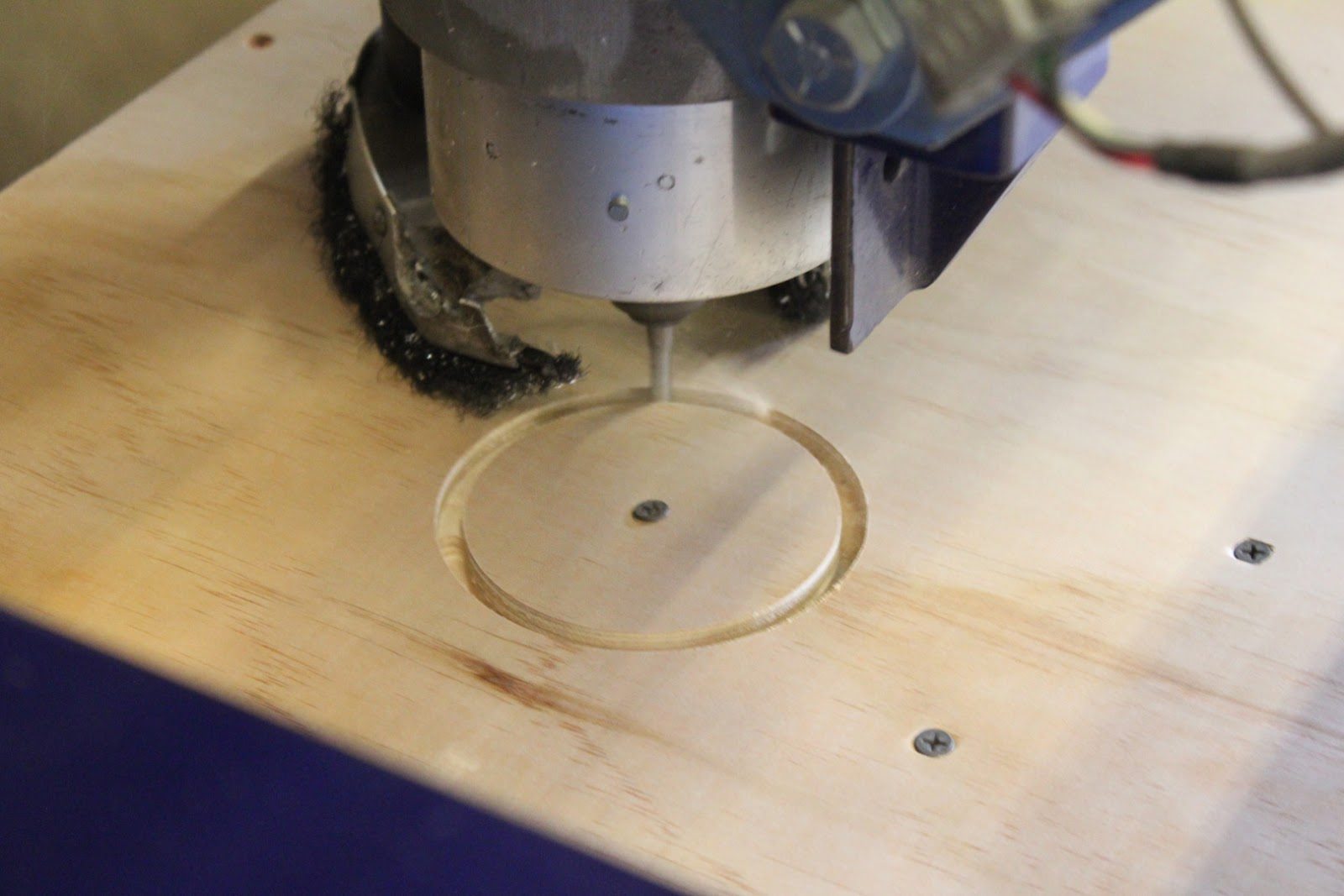
After all of the holes have been drilled the next step is to cut out the internal lightning holes.
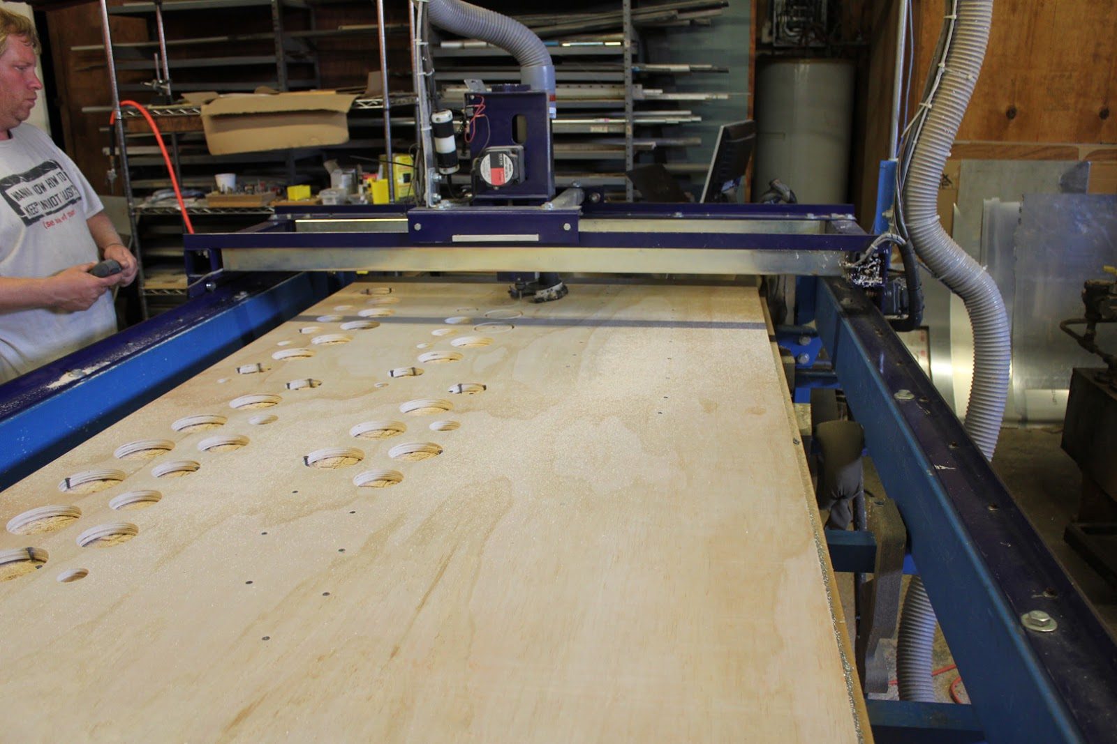
In this picture here we can see Jason capturing the center plugs and removing them and then simultaneously screwing down the perimeter of a few holes of each bending jig to hold it in place during the cutting of the outer profile.
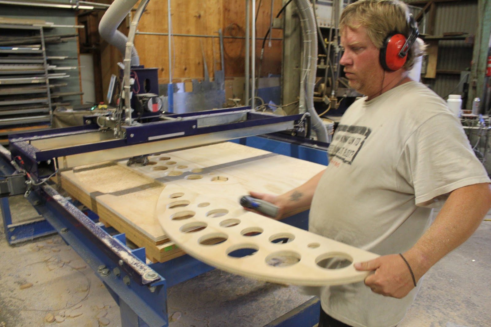
With cabinet grade plywood and a fresh carbide router bit. There is virtually no sanding required of any of the jigs. Once they come off of the router.
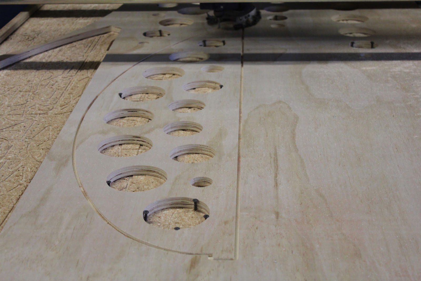
This is the upper rib bending jig being cut out. The router cuts a depth of .26 inches each pass requiring 3 complete passes to cut out each part.
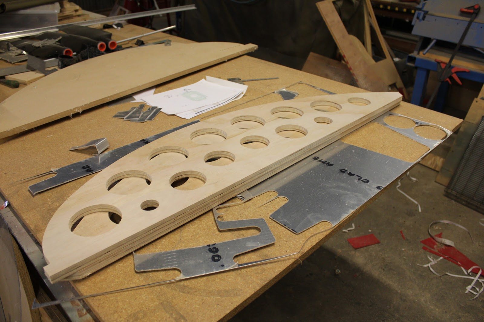
In the upper left side of the picture you see the original prototype bending fixtures made from MDF. The plywood with the lightning holes is nearly half the weight of the original MDF bending fixtures. The MDF was used on the prototypes because it took over a dozen tries to get the profile exactly perfect and we went through several sheets of MDF before we were able to come up with the bending profile that translated into the exact shape of the rib. Once the spring back was taken out of the aluminum tube.
September 7, 2015 Machining the forward and aft spar rib fittings
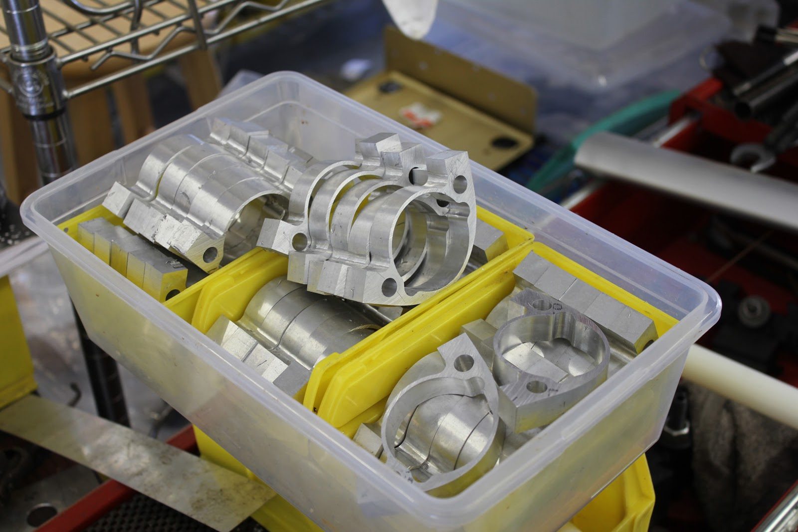
Over the holiday weekend we were in the machine shop making parts.
These are the forward spar rib fittings part number 57-70-01. We also refer to it as the rib tube pocket fitting.
These have gone through machining step 1, and are getting ready for the next phase of machining.
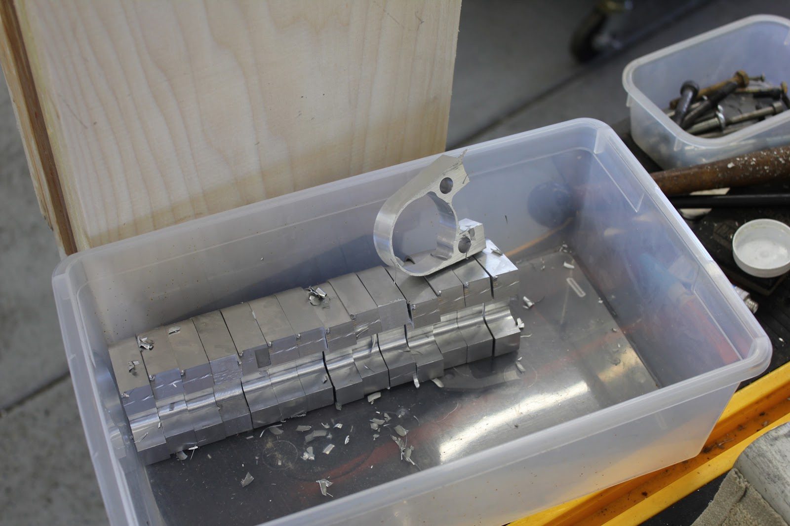
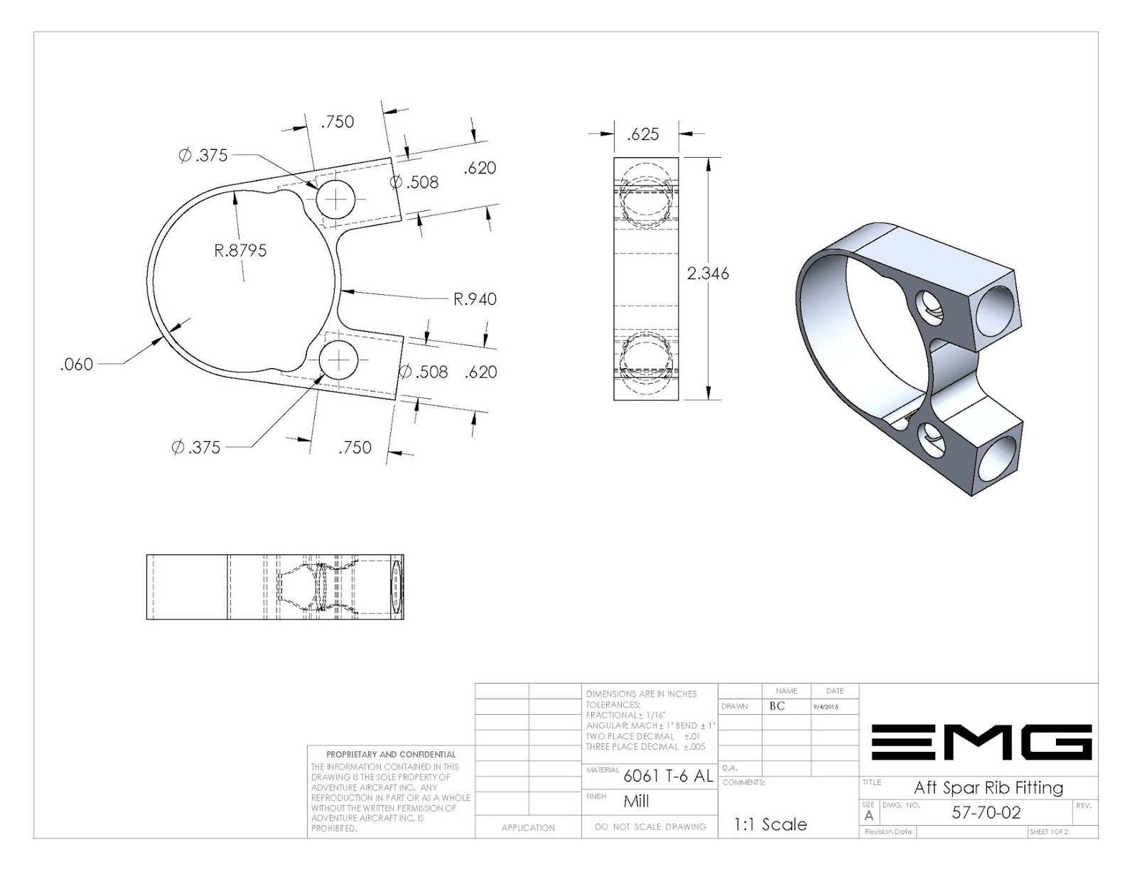
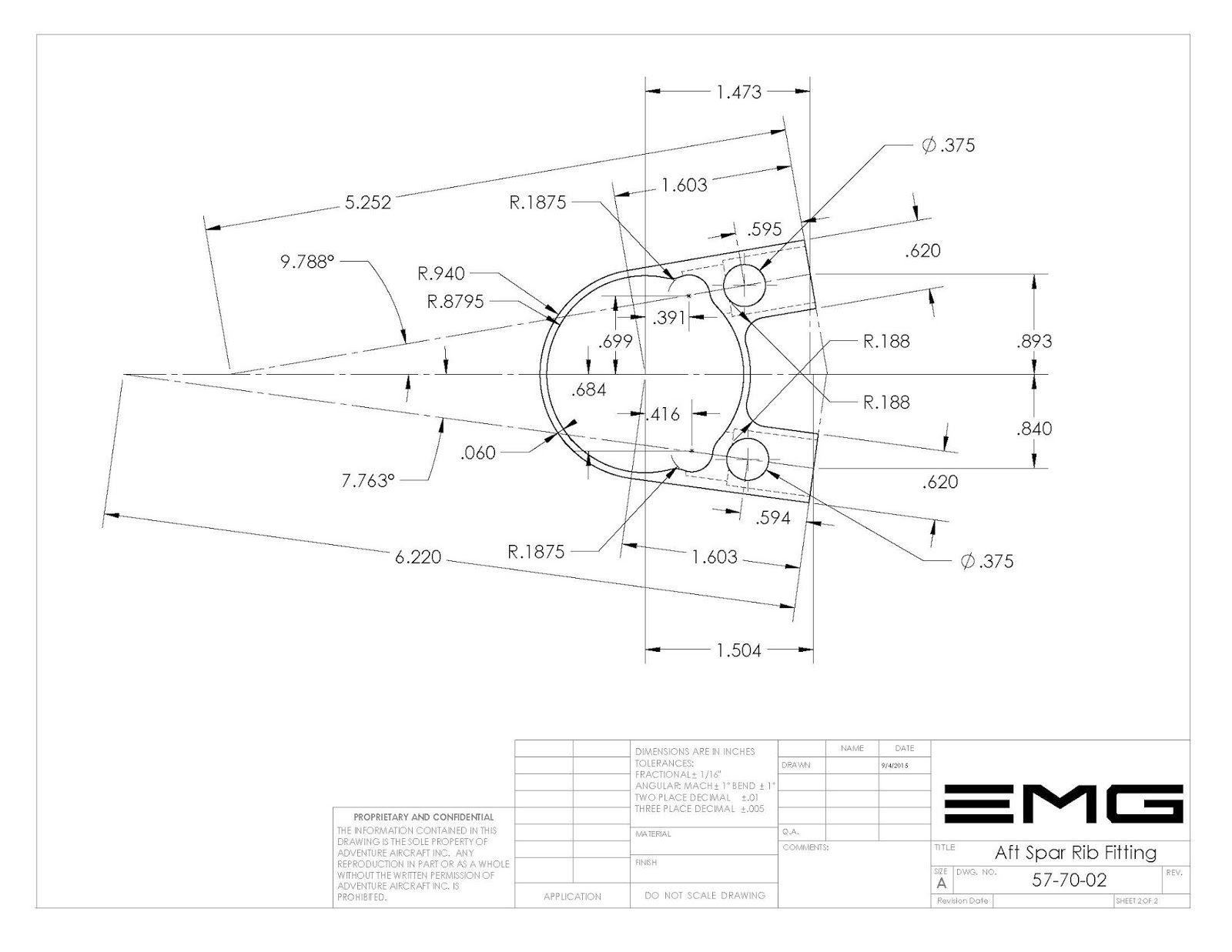
These are the aft spar rib fittings part number 57-70-02.
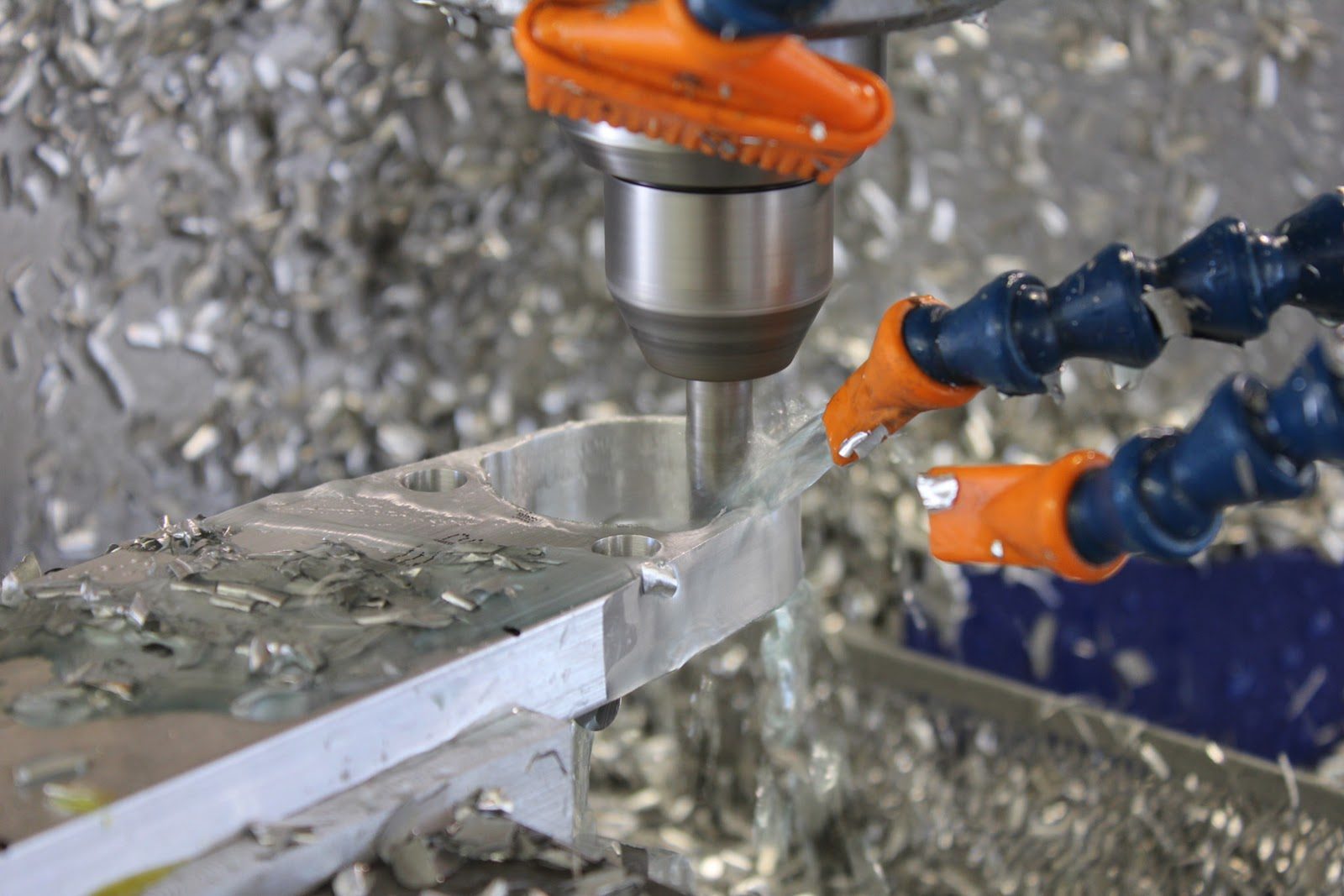
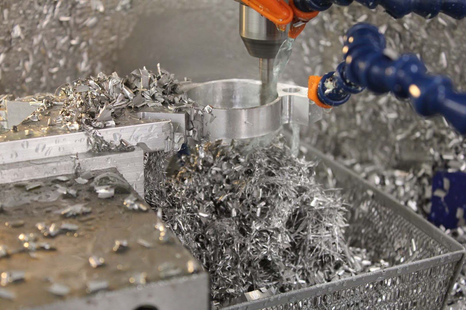
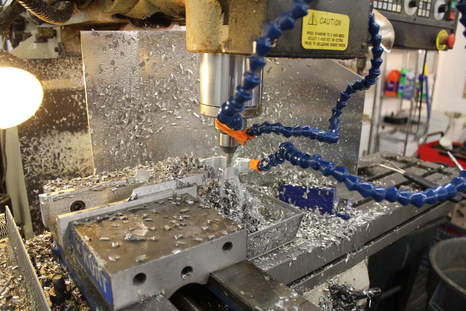
In this picture here you can see step one in the machining of the aft spar rib fitting.
The parts are machined from solid billet and are machined in such a fashion so that the complete part can be machined with the minimal amount of steps and tool change operations.
The milling machine cycle time on this operation is about 25 minutes.
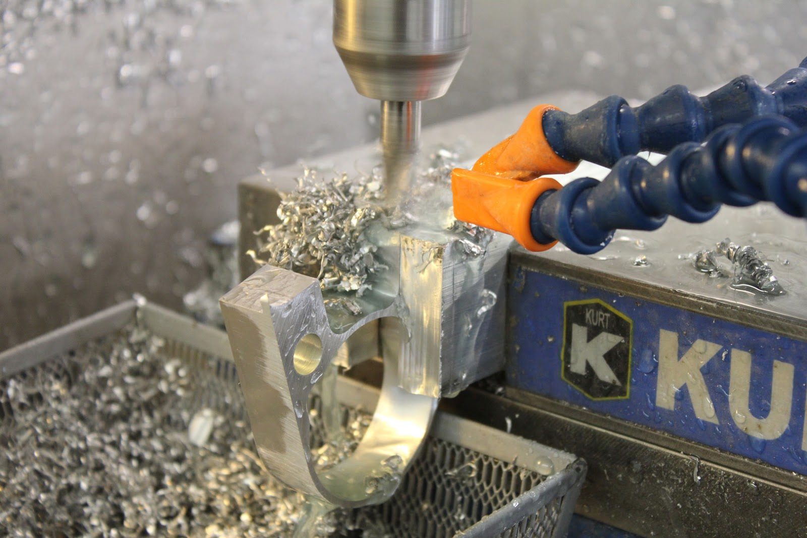
Once the profile of the fitting has been cut out the fitting then has to be re-positioned to bore out the socket on the end of the fitting that the one half inch diameter rib tube will be inserted into.
This is a step the machining process that includes a lip that properly position is the rib tube
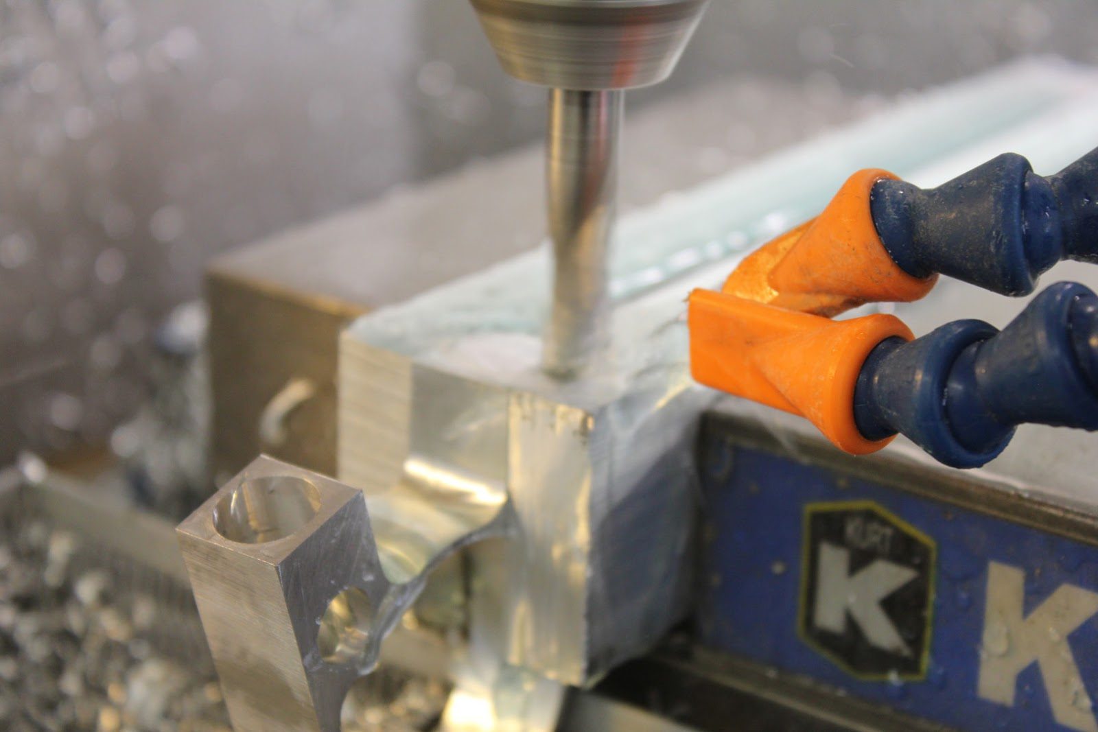
After completion of the pocket on one end of the fitting the part is rotated to the other leg and a duplicate pocket is placed into the fitting.
The milling machine cycle time on each one of these pockets is approximately 2 minutes.
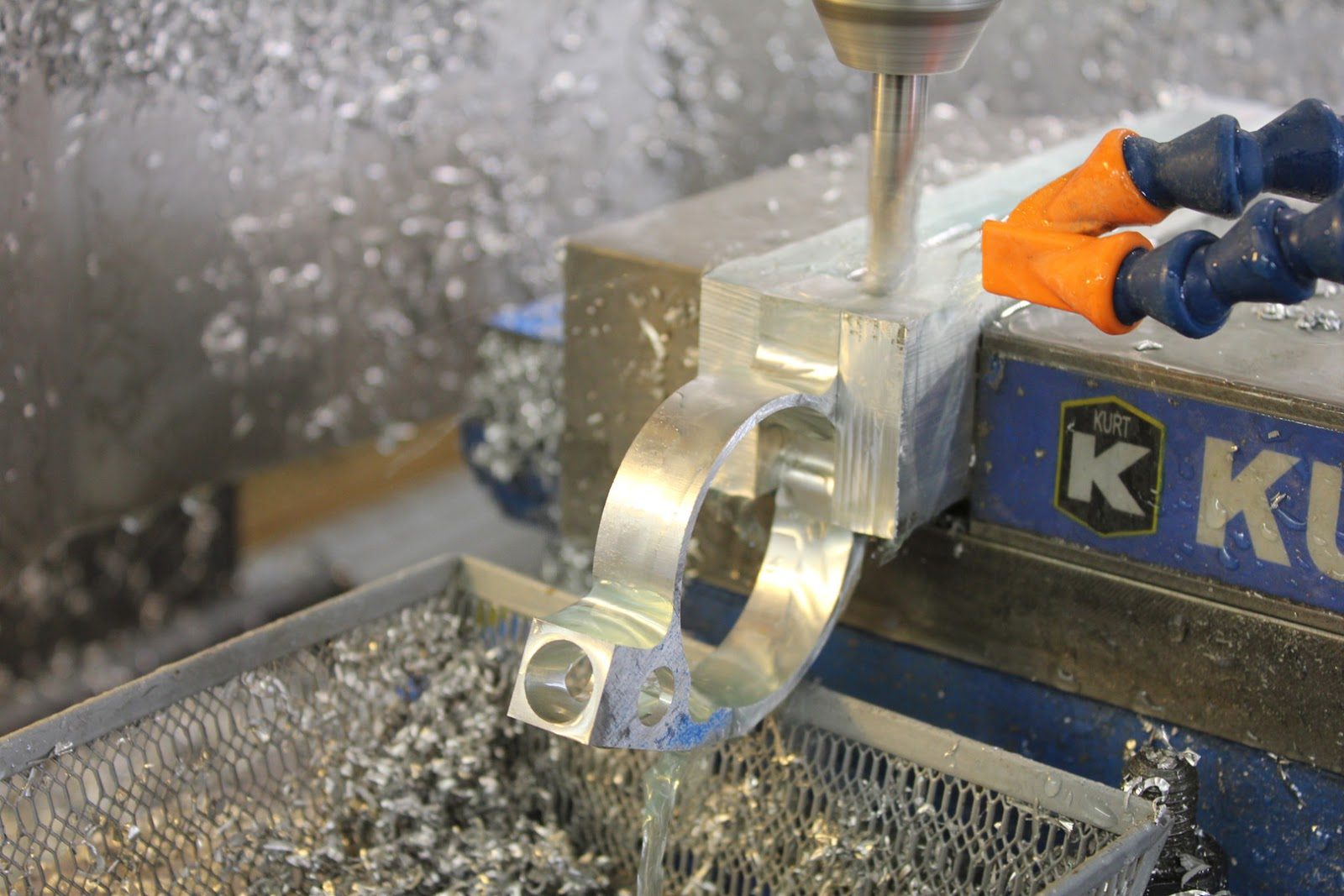
The pockets are required to be machined into the forward spar fitting just like in the rear spar fitting.
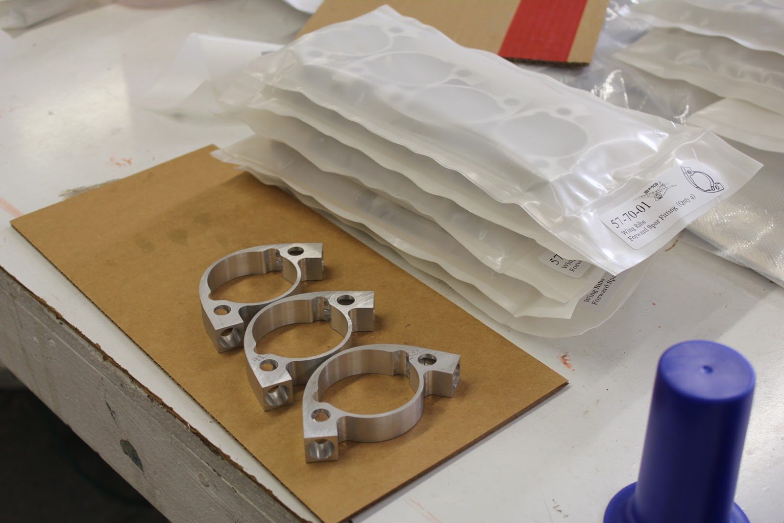
Once the parts have finished the machining process. They are inspected and then packaged to protect them from damage, wear, and corrosion.
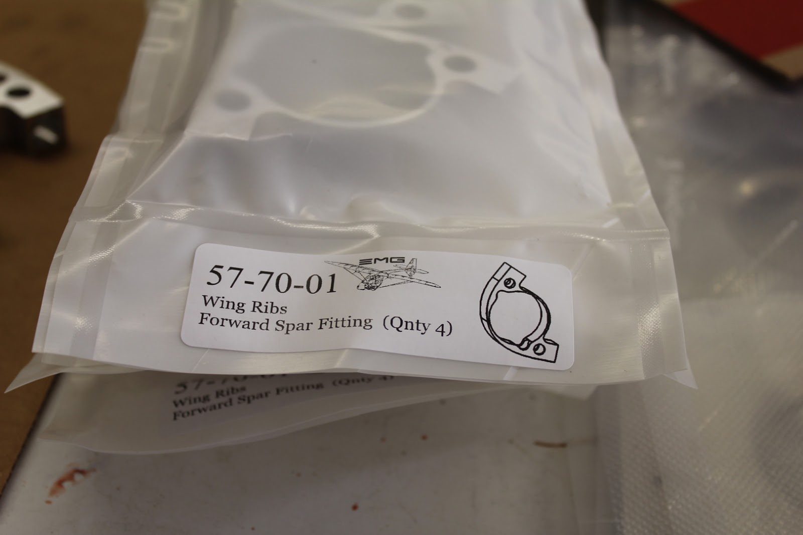
In addition to protecting the parts they are also labeled and placed into inventory.
The builders database has to also be updated with the most current drawings.
In addition to the PDF files for the drawings of each component. There are also E drawings and DXF files that will allow the builder with the capability to manufacturer any of the components.
Although it’s not likely that a part like this would be undertaken for the few parts that a builder has to build himself.
The drawings provide lots of additional data should the builder have questions about how the part is to be manufactured or for inspection purposes.
September 5, 2015 Manufacturing of components for Fuselage Boom Assembly
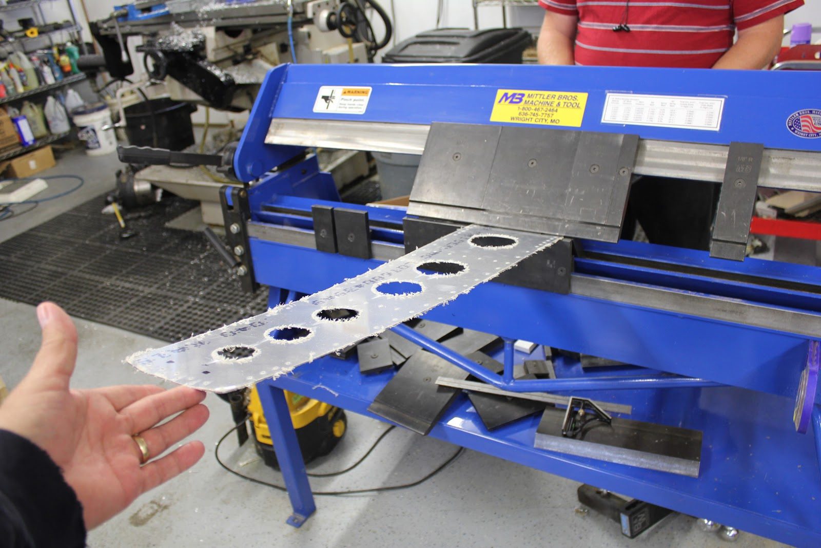
As we are putting drawings together. We also take pictures of the manufacturing process so that we can have as much reference material as possible for the future manufacturer of any of the components on the aircraft.
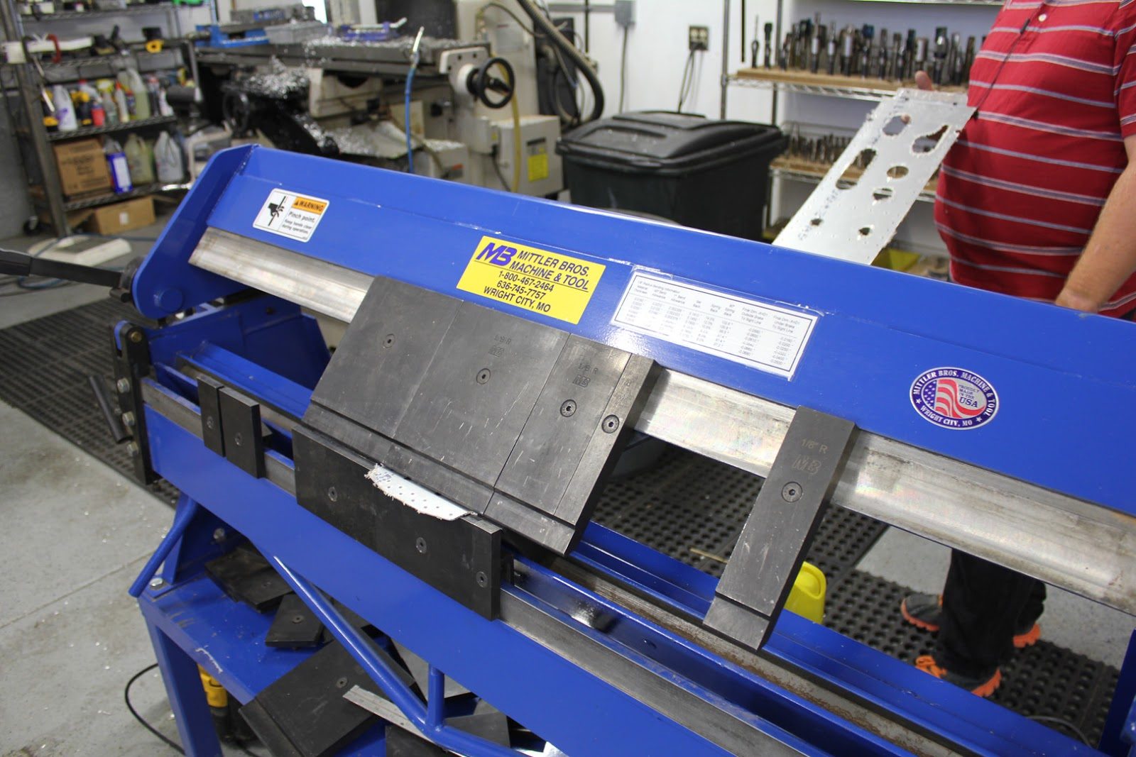
The orientation on how the part fits into the finger brake changes the dimensions on each bend. Orienting the part in a very specific direction in relationship to the dimensions ensures the flange is bent correctly.
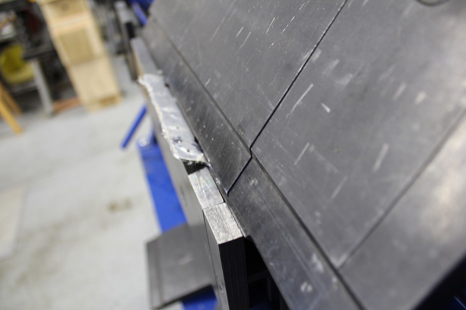
Having a visual clue as to the amount of bend in each flange also helps in setting up each part for the bending process.
September 2, 2015 Bending Fuselage Boom Assembly Components
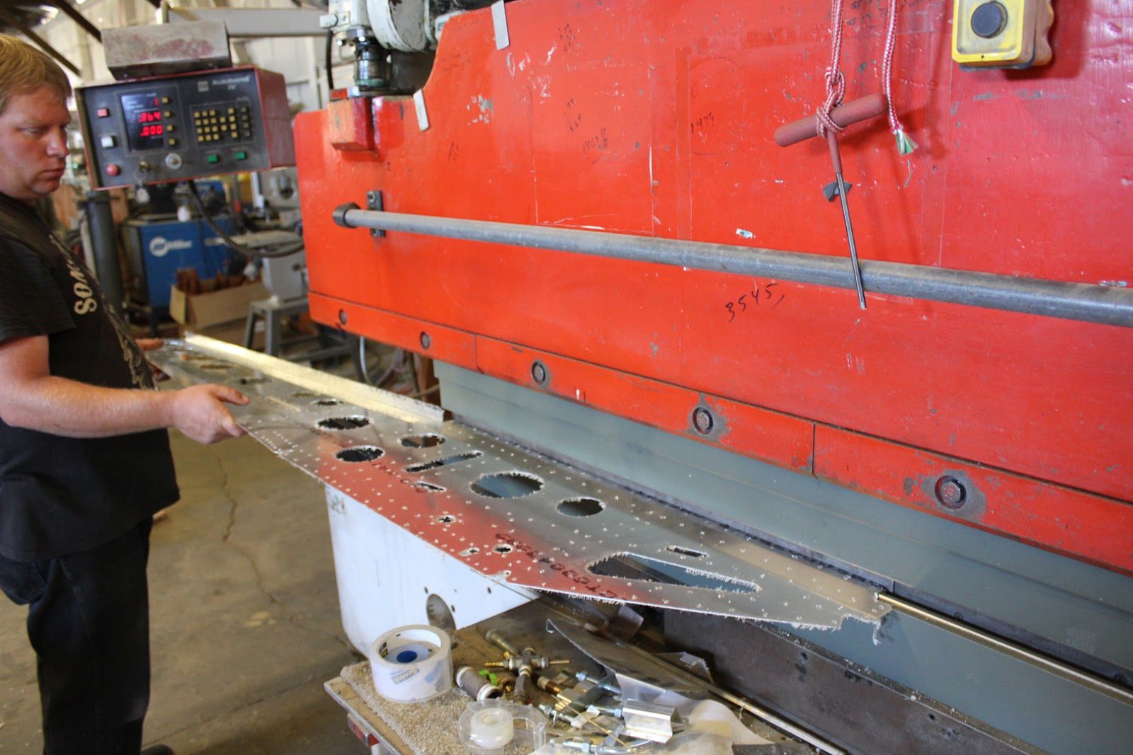
Where continuing to work on the fuselage boom assembly kits. In this picture here we can see Jason positioning one of the largest components on the fuselage boom assembly which is the fuselage boom side.
We have designed the fuselage boom to be able to be bent using 6 foot long dies.
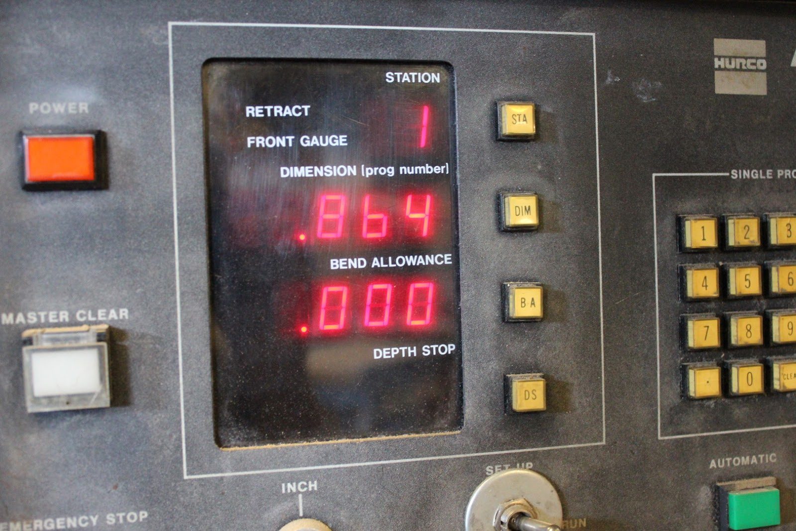
The press brake has a CNC back gauge which is really phenomenal in establishing repeatability during the bending process. We can go from part the part and simply punch in the new dimension for each flange. We do however try to design each one of the parts so that most of the flanges are identical dimensions which helps during the mass production phase so that we don’t end up having to reset the back gauge nearly as often
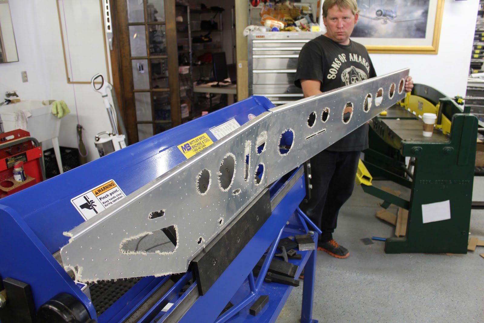
Every bend on the fuselage boom assembly uses a 1/8 inch radius die for the bending. This radius works really well through most all of the material thicknesses up to about .063 when using 6061 T6.
Both the press brake and the finger brake that we use in the shop are set up with 1/8 inch radius dies. For complex components like the fuselage boom side. It requires that we bend 3 of the bends on the press brake and 3 on the finger brake.
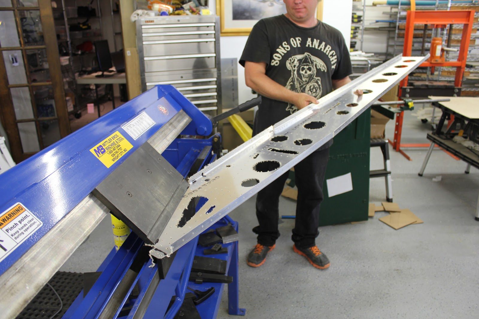
In this picture here we are finishing up the 2nd of 3 bends on the fuselage boom side part number 53-20-10
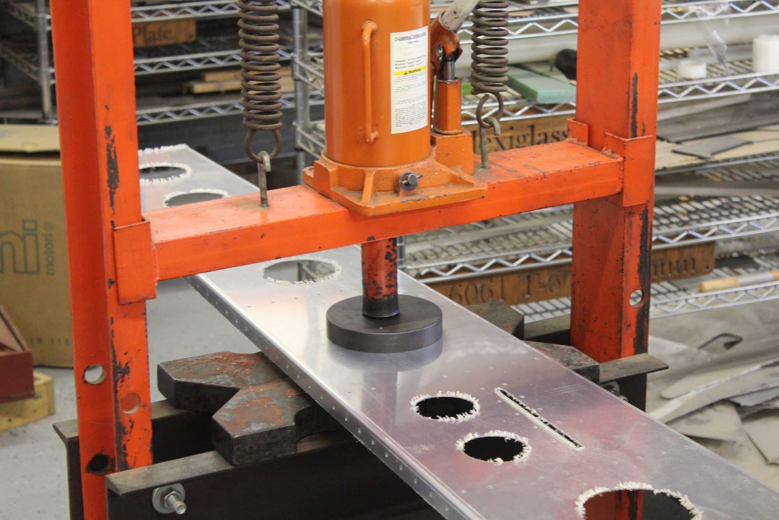
After all of the flanges have been bent and checked the next step is to flange. Each one of the lightning holes, which adds a significant amount of strength. We use a hydraulic ram, especially on the large diameter holes like the 4 inch hole that we aren’t dimpling here.
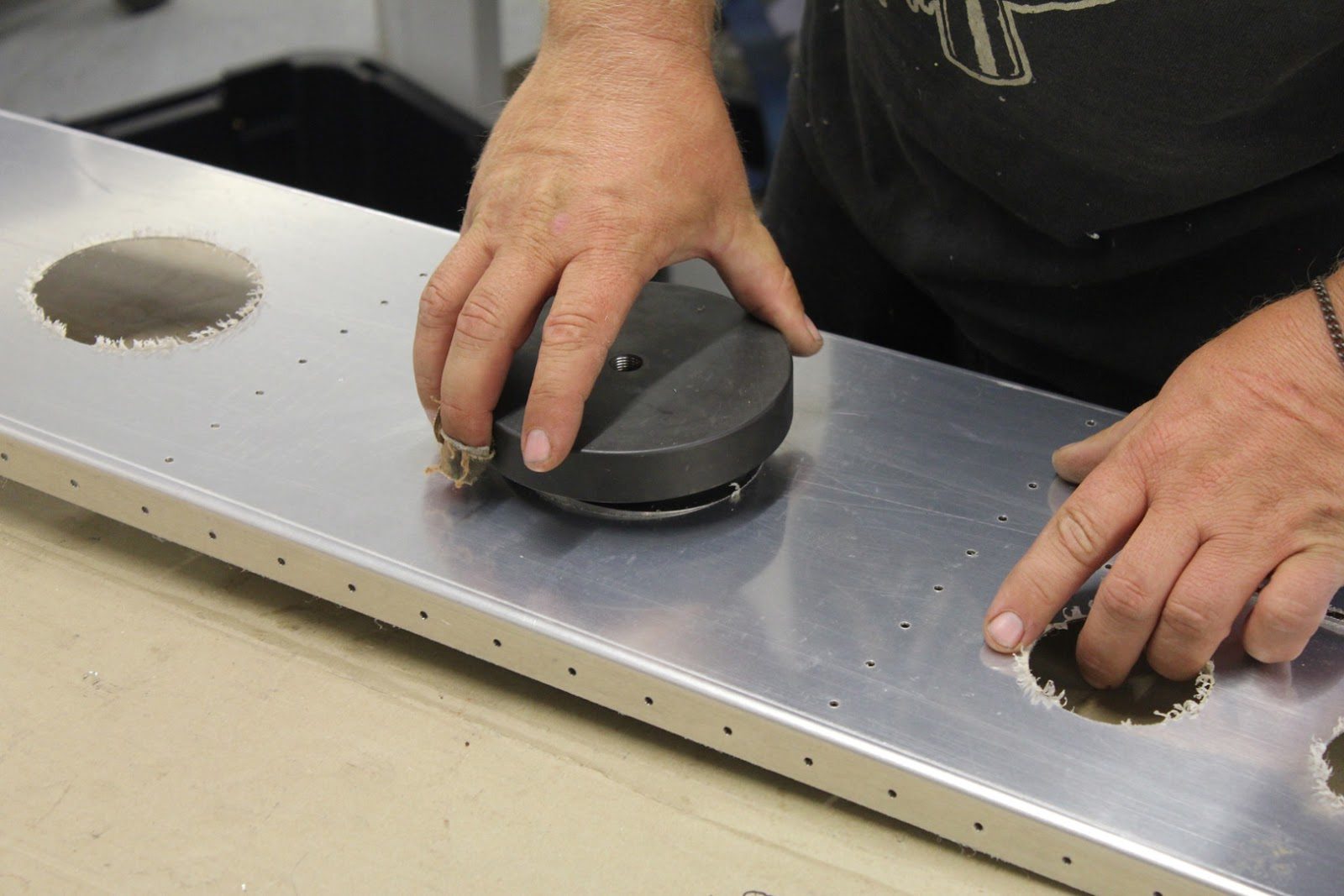
All of the dimpled guys have to be hand assembled and screwed together with the male and female die as well as the Cutter died. It’s on the inside.The cutter die will cut the holes. If they’re not already there. However, we use it to align the previously CNC machined holes as it reduces the total amount of wear on the dies and makes it simpler to dimple each hole. By reducing the total amount of force necessary to cut through the .040 thick sheet metal.