Shop notes · February 2016
EMG-6 "Shop Notes" February 2016
Brian Carpenter · Rainbow Aviation
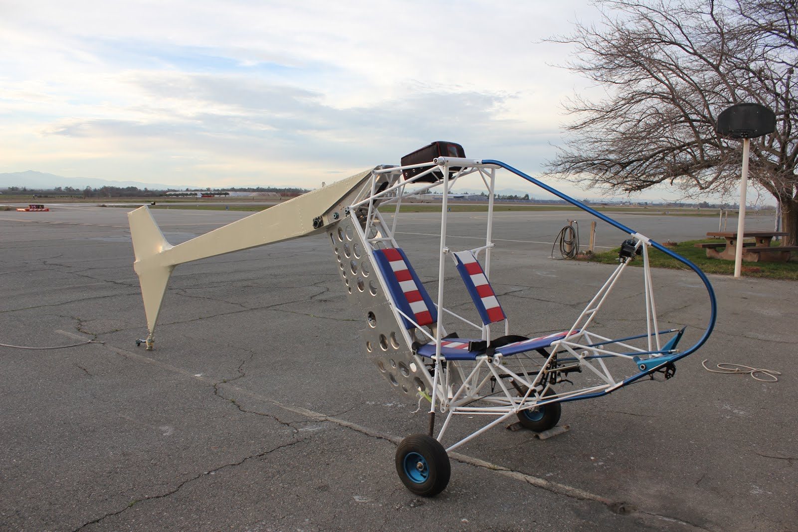

“EMG-6 Shop Notes” is a day-to-day accounting of what’s going on in the shop with the EMG-6 Electric Motor Glider.
February 29, 2016
“Spark Plugs and The Rotax Engine: Part 1” Sport Aviation / Experimenter “Technically Speaking” Article February 2016
February 26, 2016
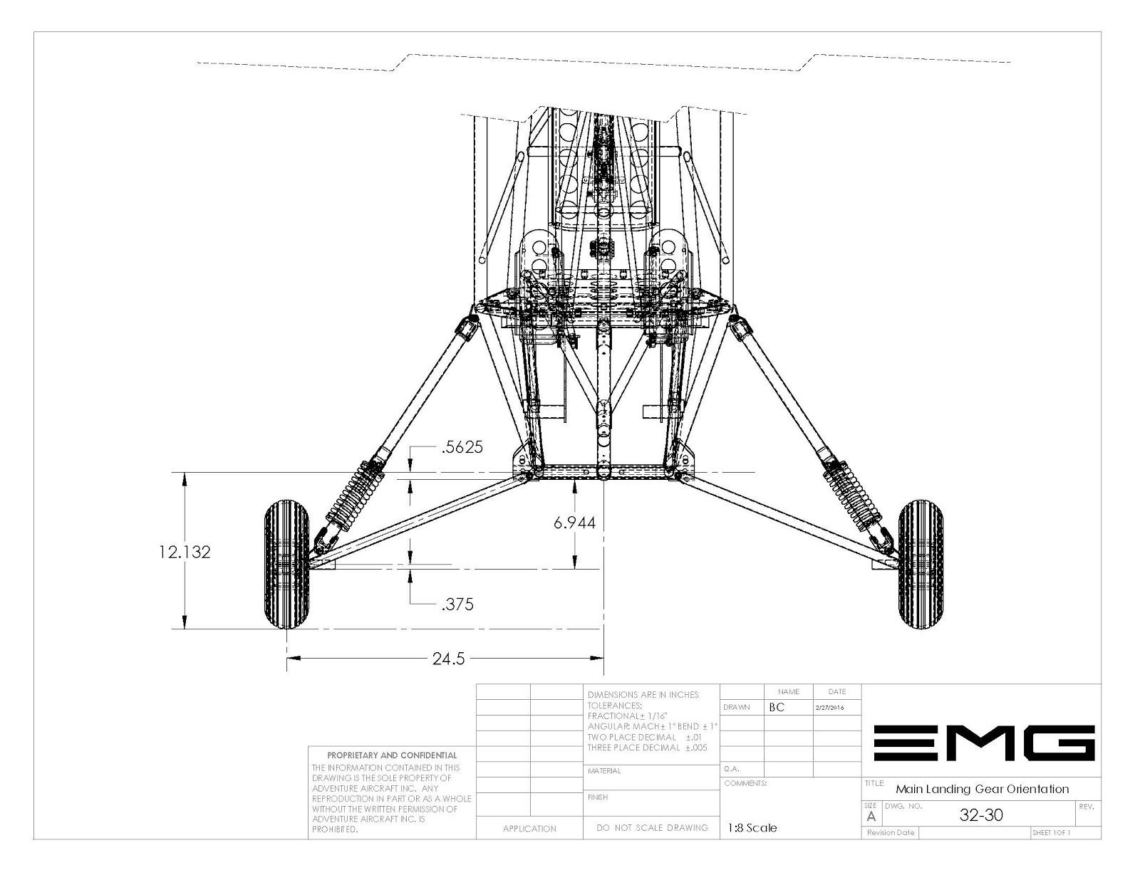
More files added to the builders database for the main landing gear assembly.
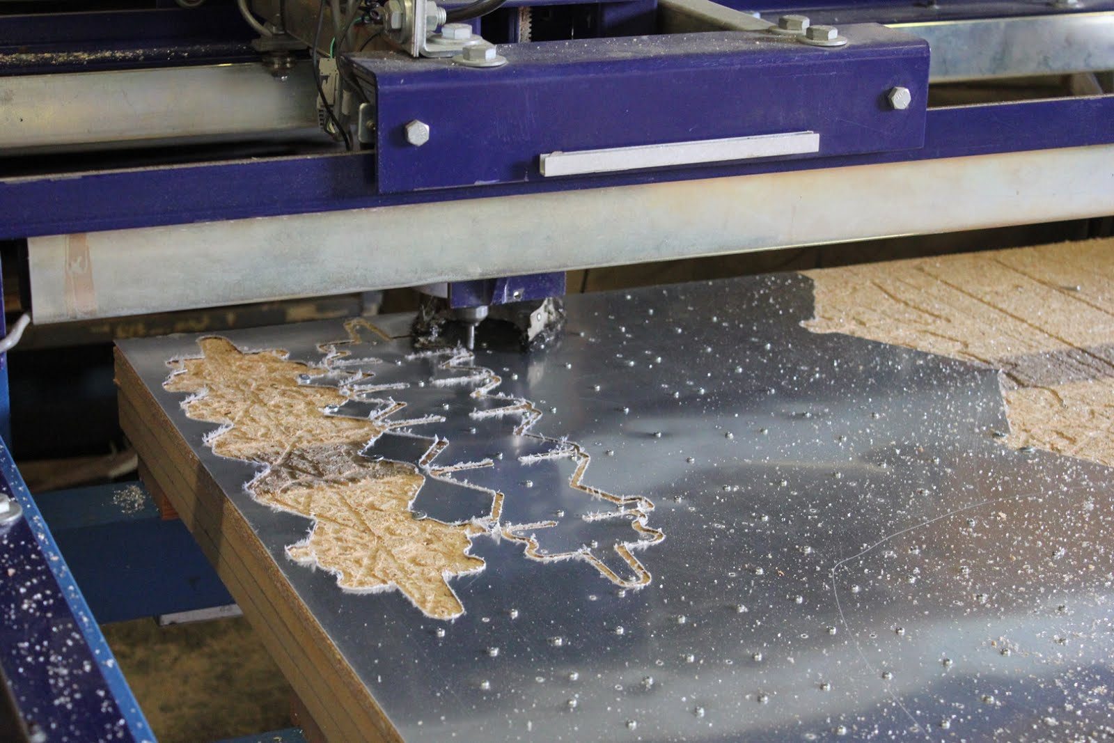
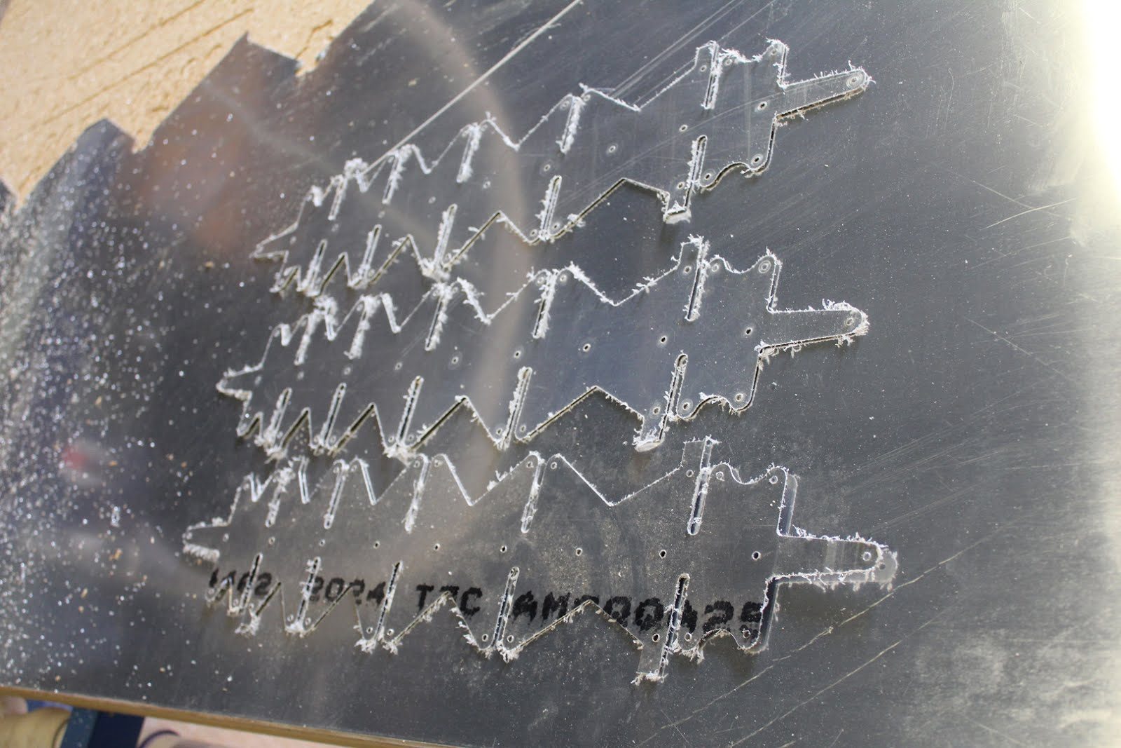
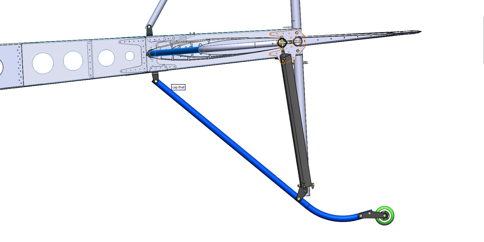
The ribs are manufactured from .016 2024 T-3 aluminum (very light). A total of four pieces per side are required.
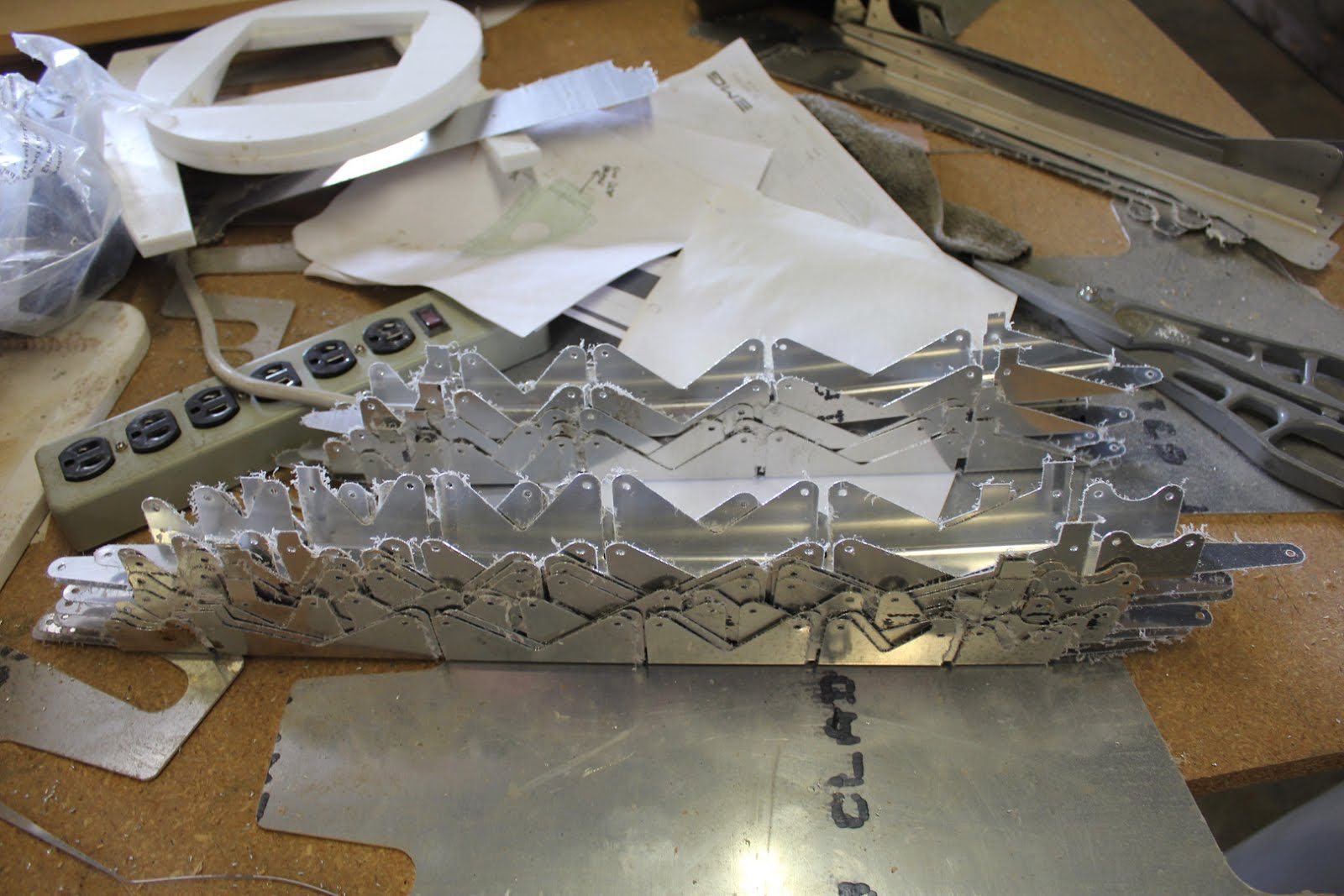
The ribs are bent with two 90° flanges creating a surface for the fabric to be attached to.
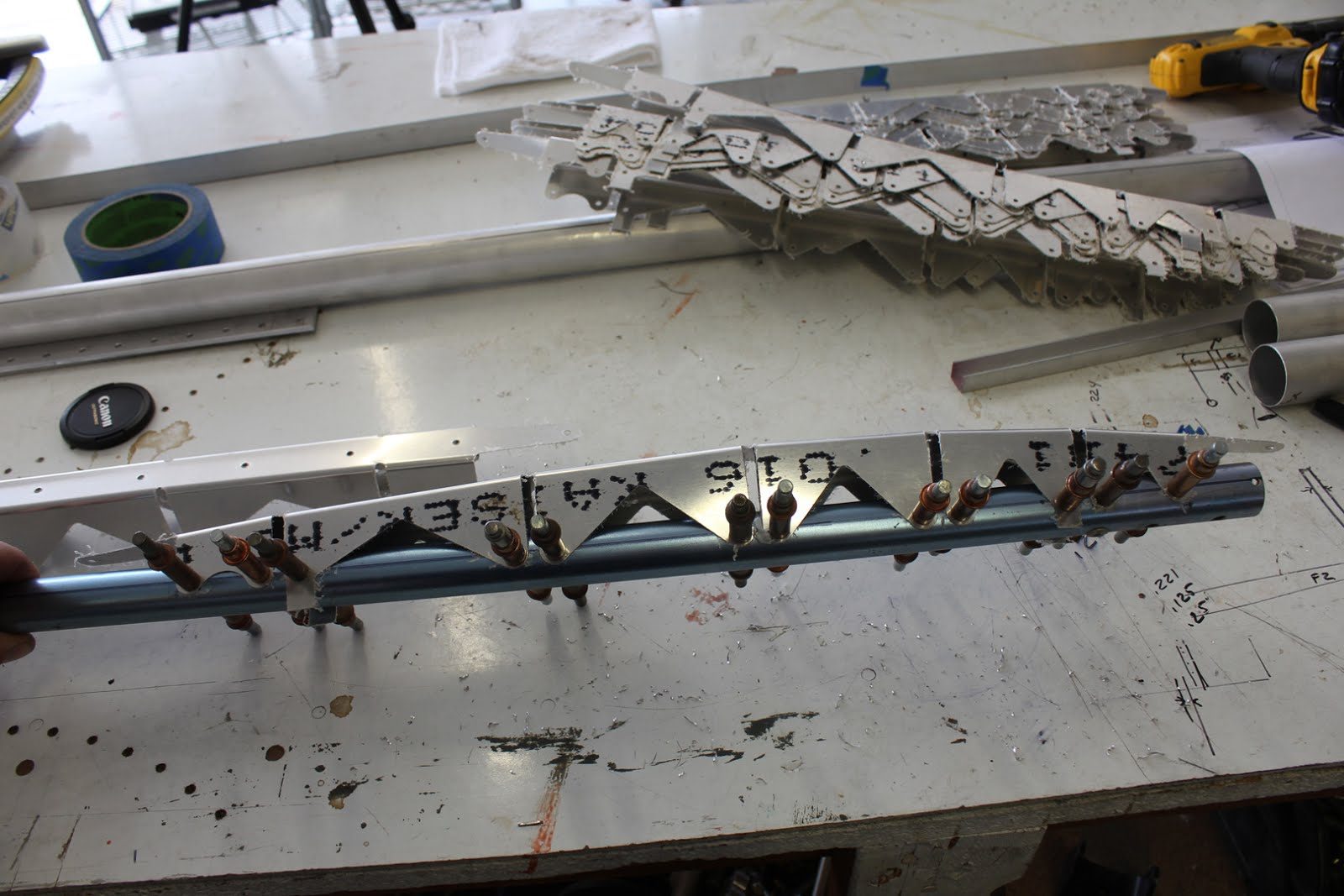
The ribs can be simply attached to the primary structure using a pinch pop rivets. The geometry of the legs creates the airfoil shape.
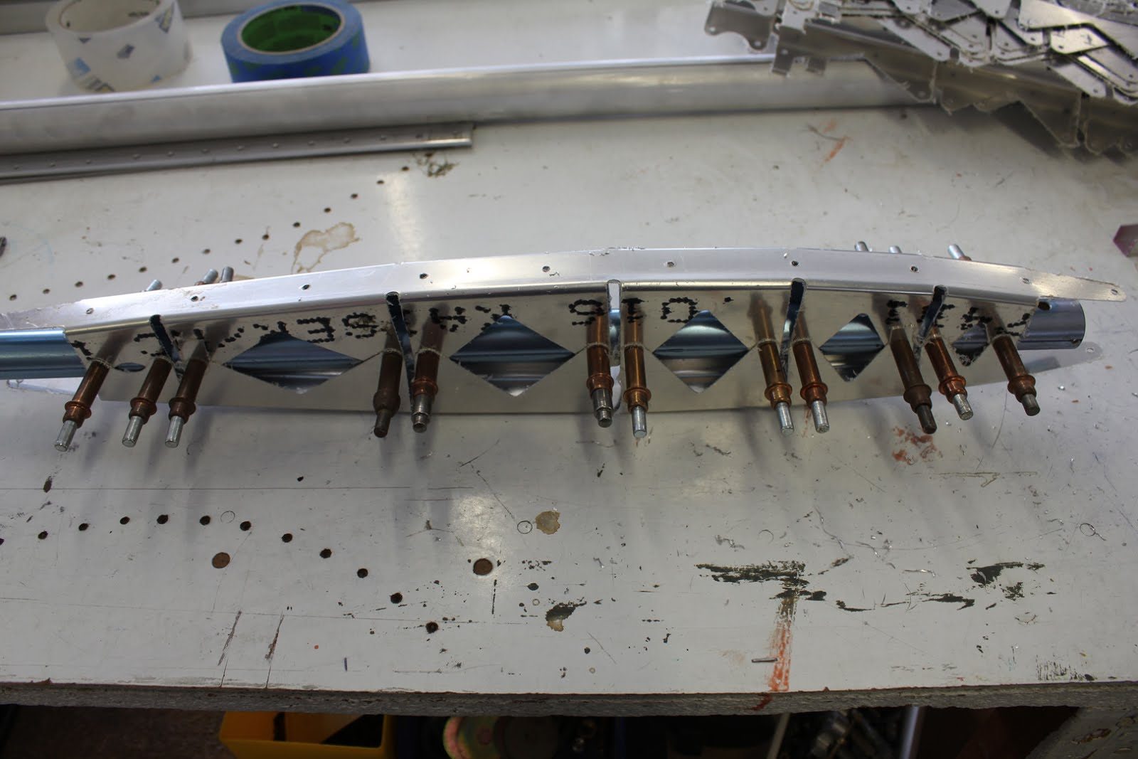
With one rib on the top and one rib on the bottom the airfoil shape is complete.
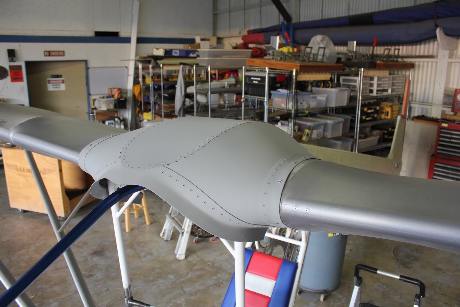
Fuselage Center Section Fairing Complete
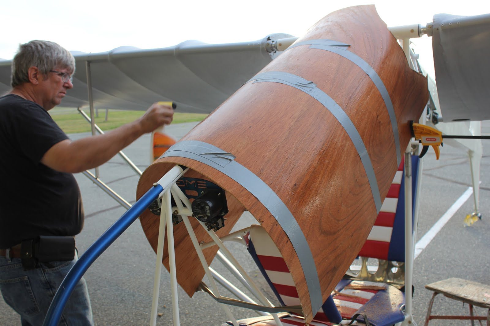
We’ve completed the center section fairing and have it primary ready for paint. All of the nut plates of been installed into both wings. You can click on the link to the fairing page and check out the complete process of how we manufactured the center section fairing.
February 25, 2016
Carol adds two more flights on the EMG-6. She flew once during midday and again towards the evening accumulating about another hour and a half of flight time. She got to practice multiple takeoffs and landings in the three point and the wheel landing configuration. She got to experience the hands-off capability of the aircraft by making two circuits of the traffic pattern without touching the stick.
February 24, 2016
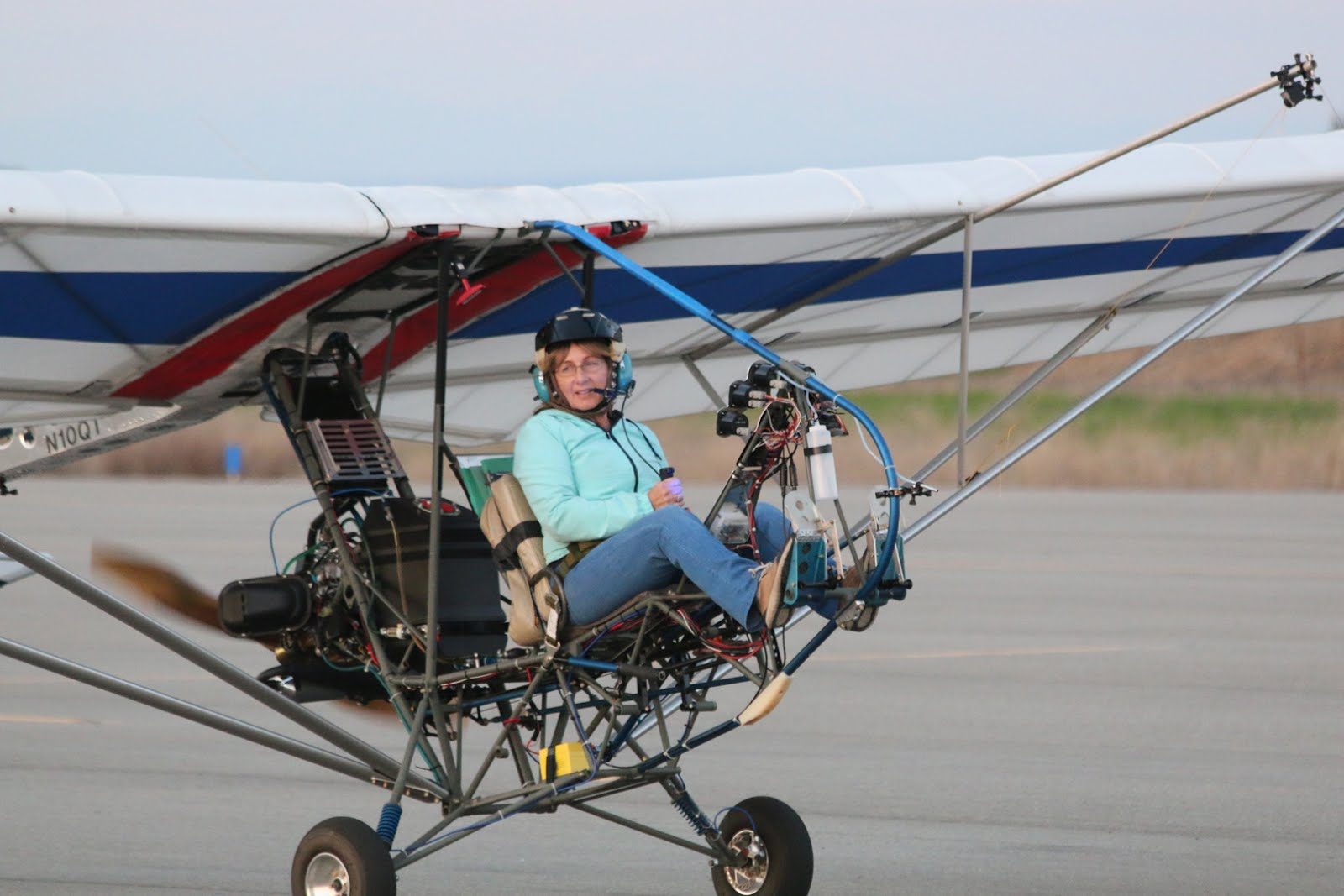
Carol Carpenter First Flight
Carol Carpenter becomes the second person to fly the EMG-6. The smile says it all. Everything went exceptionally well. We won’t elaborate on her flight as she is going to create a blog post from her perspective and we will post that the next day or so.
February 23, 2016
We have been working on some carburetor fuel issues on the Polini 250 powered EMG-6 prototype #1. This is the first time this year with have the airplane out about for flying. It was good to get a chance to get back in the air and get excited about the next phase of flight test.
Wing Center Section Fairing Progress
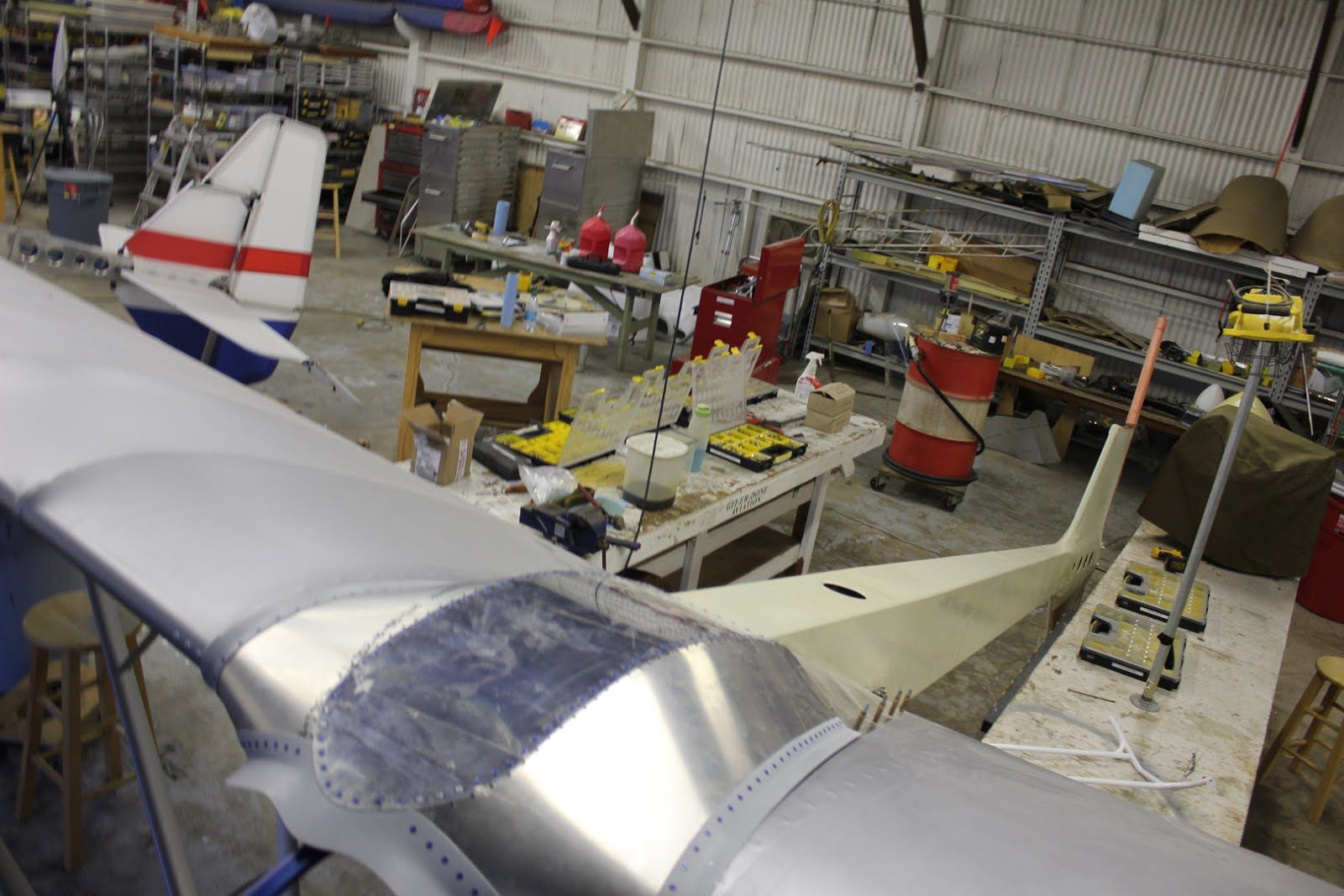
We continue to make progress on the wing center section faring. The faring itself is now complete and were getting ready for the final installation. We will need to put nut plates into the wing for the attachment and then we will be finished with the faring assembly.
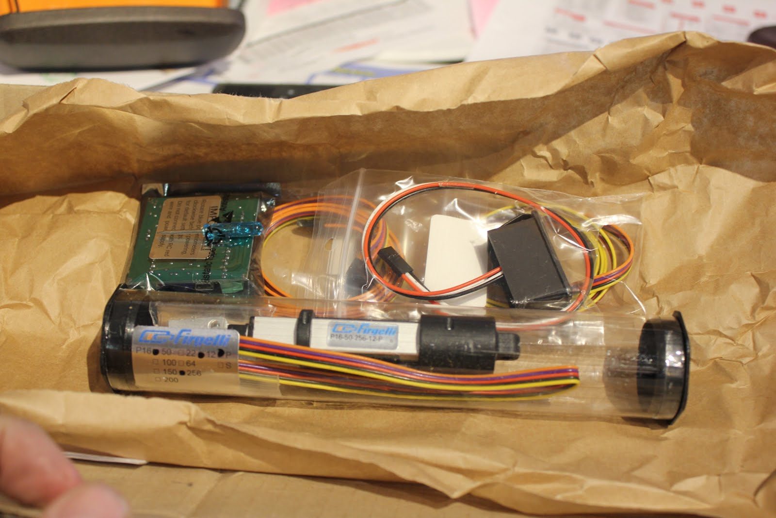
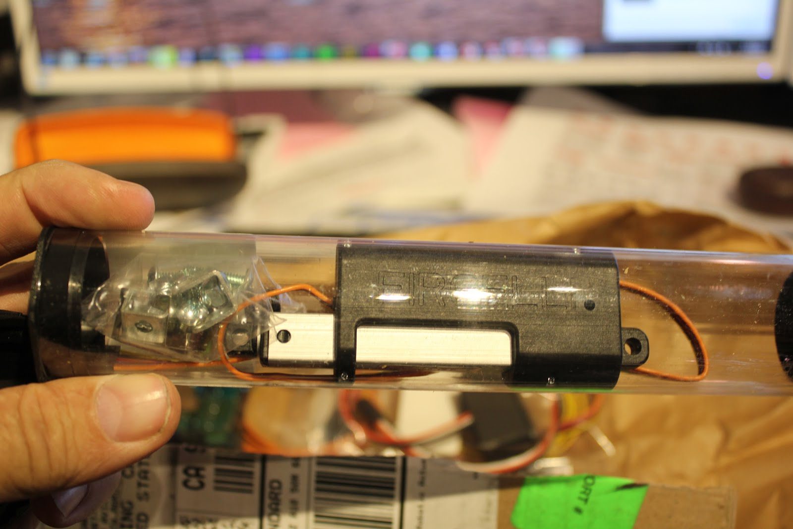
The components for the stabilizer trim system arrived from Firgelli today. The parts include the controller board, extension cables, trim position indicator, mounting hardware, and the P 16 servo
This picture gives a pretty good idea of how big the trim servo is. We will be creating an entire page on the development and installation of the stabilizer trim system as we go.
February 22, 2016
We finished up with all the customer airplanes and now have the main hangar available once again for working on the EMG-6. Today were going to be working on the center section fairing and on the pilot seat.
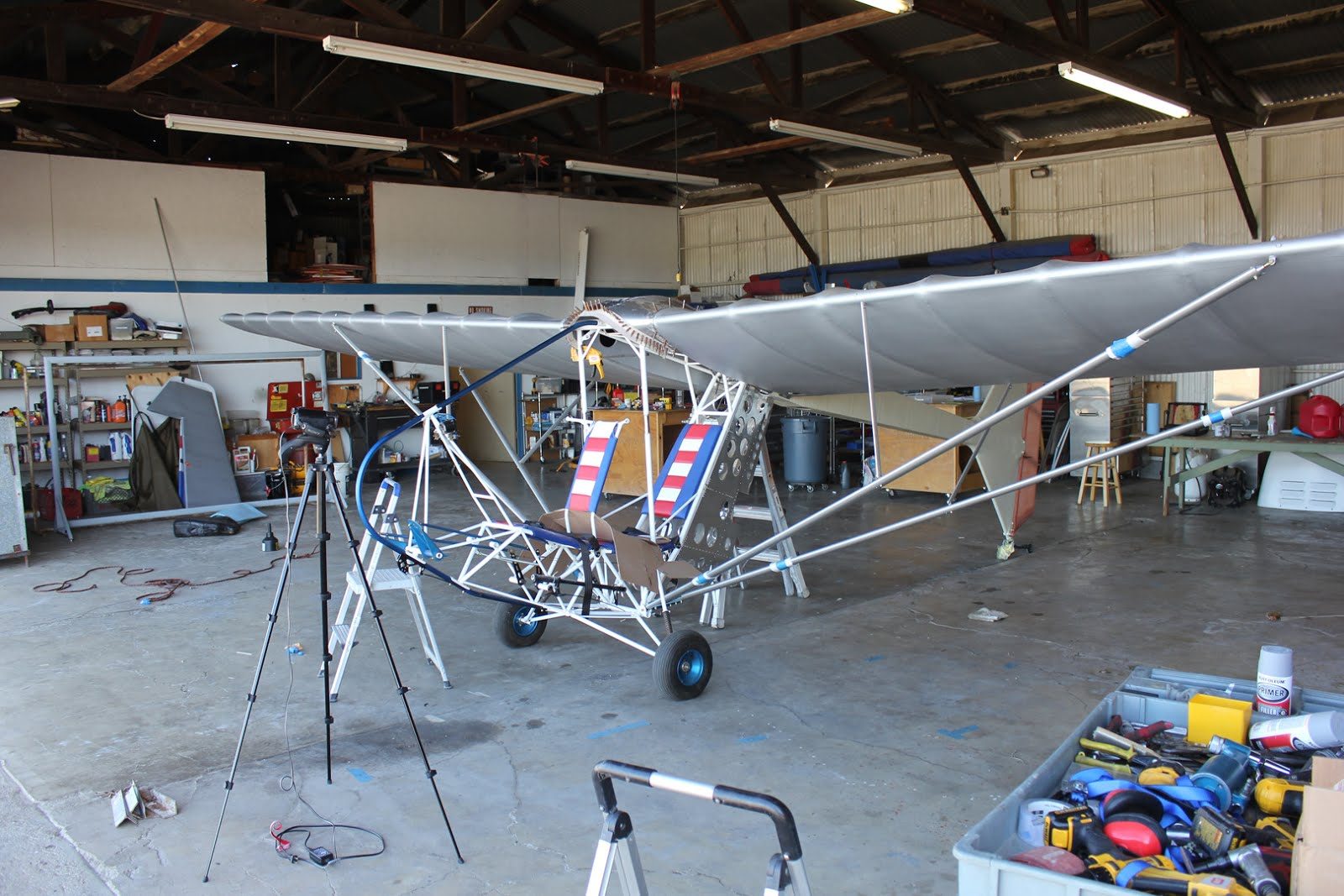
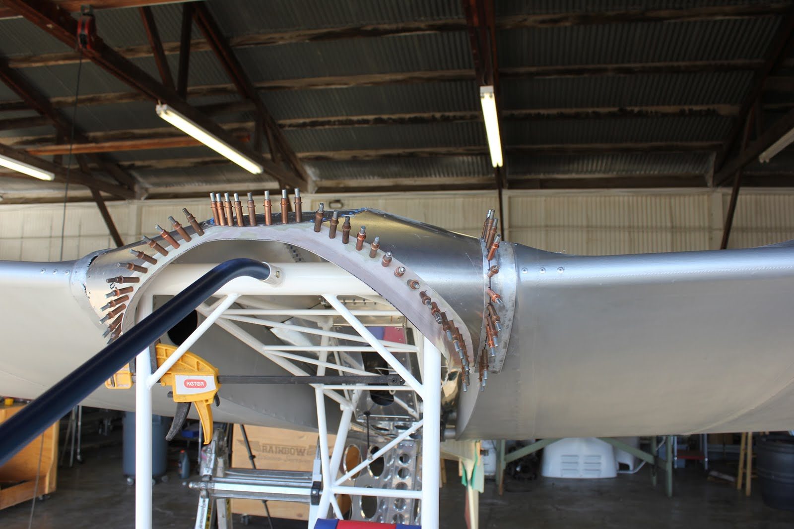
Click here to link to the fairing page.
Pilot Seatback Modifications
We have started working on the modification and the new design change to the seatback for the pilot. We will start by modifying the old design and then on prototype #3 we will start from scratch and publish the drawings and builder videos during that process.
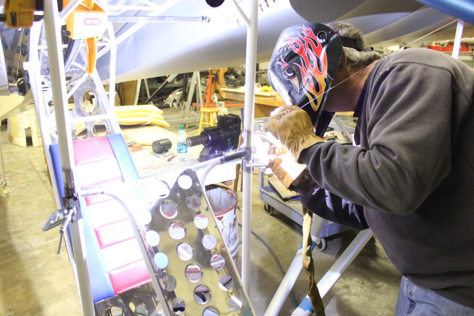
Click here to link to the seatback page.
February 21, 2016
The weather has improved and were back on the fuselage center section fairing. we have an entire pages dedicated to the manufacturing process and how we’re making this one off prototype fairing.
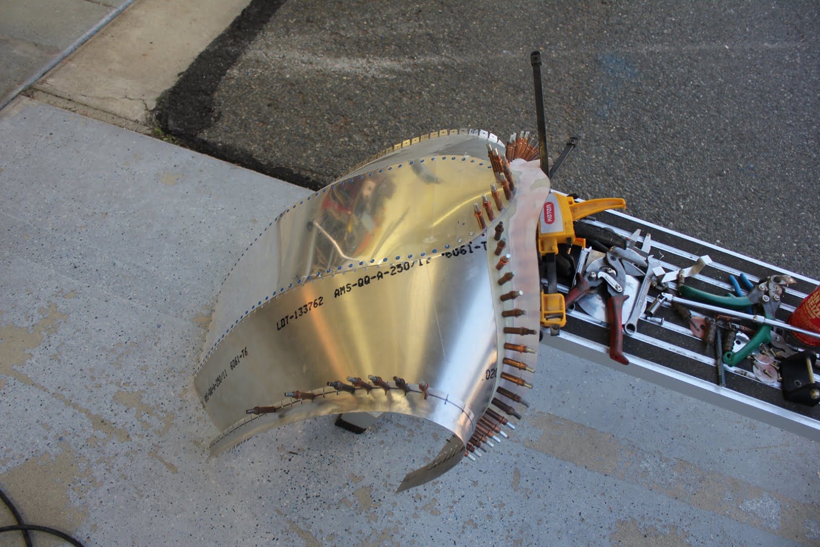
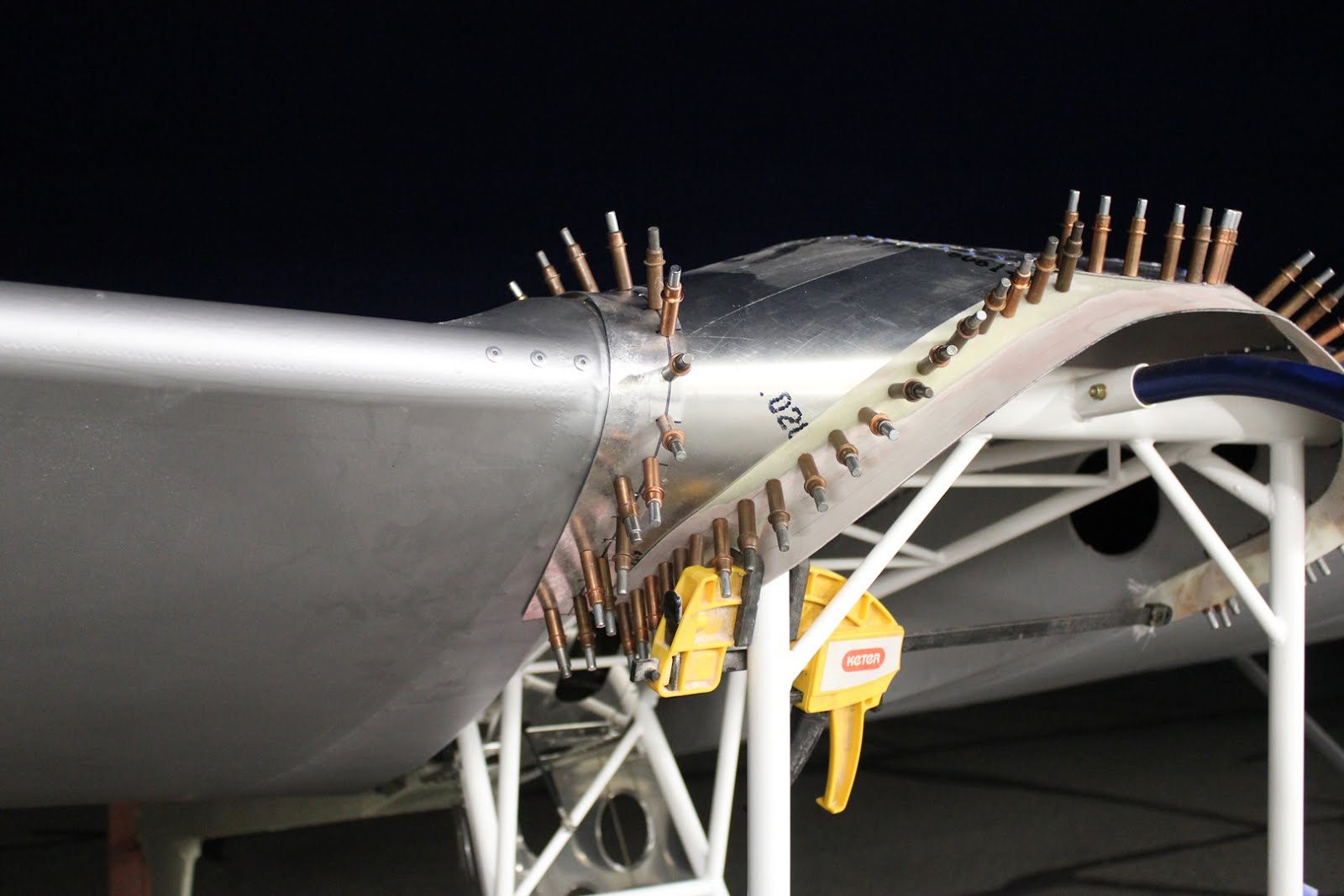
February 20, 2016
Aileron Assembly
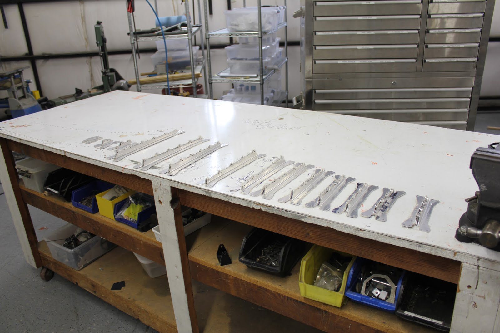
We have begun the process of building the Aileron assemblies for prototype #2. the process will take a little longer than normal because we’re going to be shooting video of the construction process as well as demonstrating the method to manufacture the ailerons without having the predrilled CNC machine ailerons spars. We will be making one video on drilling procedures for making your own ailerons spars, one video on setting up a drilling jig, and one video on the assembly procedures.
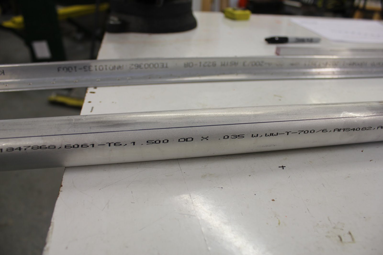
The main spars will be manufactured from 6061 T6 aluminum 1.5 0D X .035 wall
Horizontal Stabilizer Electric Trim
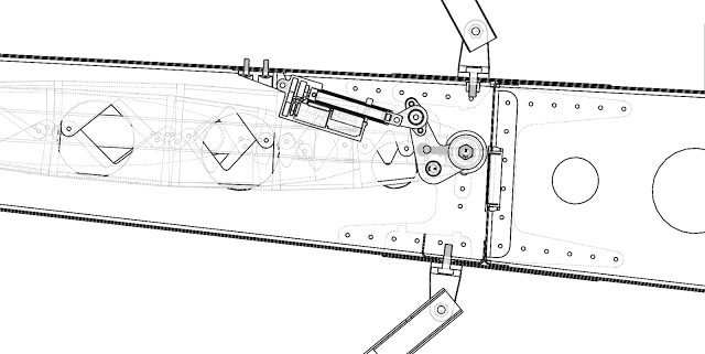
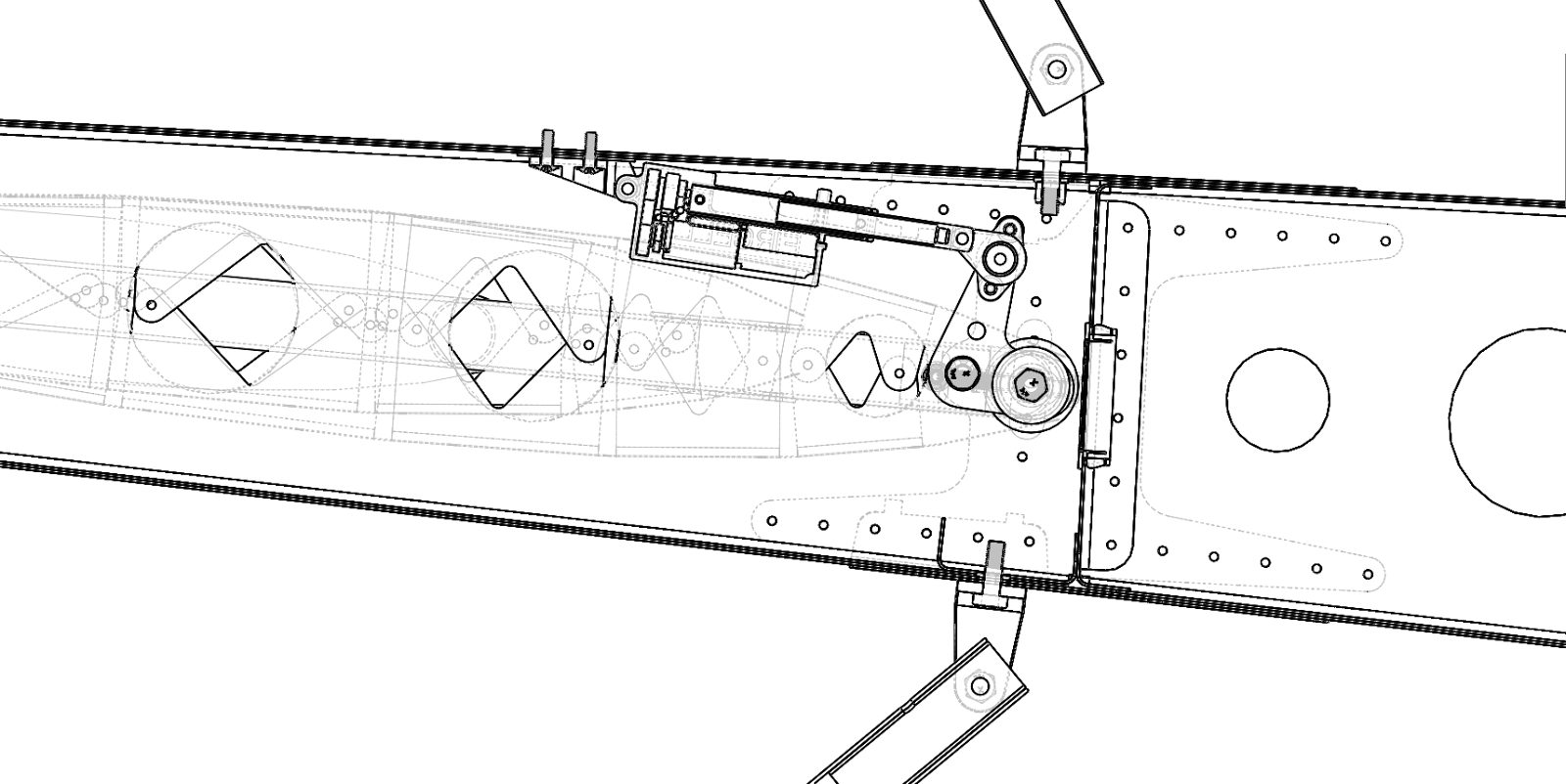
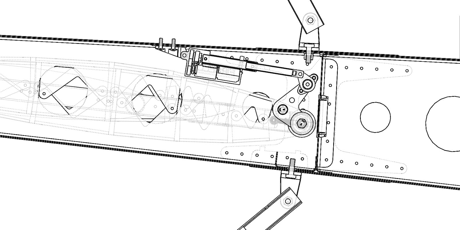
We are in a position to be able to install the new electric trim system on the second prototype aircraft. This will allow us to be able to trim the aircraft throughout its entire CG range. We have completed the design work and ordered all of the components for the prototype trim system and will be installing it in the #2 prototype.We are using a Firgelli P16 linear servo that is designed with a 256:1 gear reduction ratio and a lifting force of 300 N. which is about 67 pounds. With a maximum static force of 500 N or 112 pounds. The servo operates dual cams with a leverage ratio of 2 to 1. These cams operate bearings affixed to the rigid fittings on the leading edge of the horizontal stabilizer. The P 16 linear servo weighs a mere 140 g. About .3 pounds. The linear servo is operated from the cockpit with a position and forget rotary switch that drives the trim to the selected position without having to hold the switch. The geometry of the trim system is designed to be able to operate through its full 50 mm travel without interfering with the elevator push pull tube that runs through the center of the fuselage boom assembly.
Nose Down Position
Neutral Position
Nose Up Position
The system is designed as a retrofit to an EMG-6 built without stabilizer trim, and can be added as the aircraft is built, retrofit later, or built as a trim ready set up. This will allow you to put all of the parts into the aircraft initially to simply bolt in the electric trim system later. The trim positioning cams operate by moving 2 roller bearings, 1 bearing located on the cam arms and the other bearing operating as a guide along the slot in the side of the fuselage boom. In addition to nylon washers provide bearing surfaces on either side of the fuselage boom assembly.
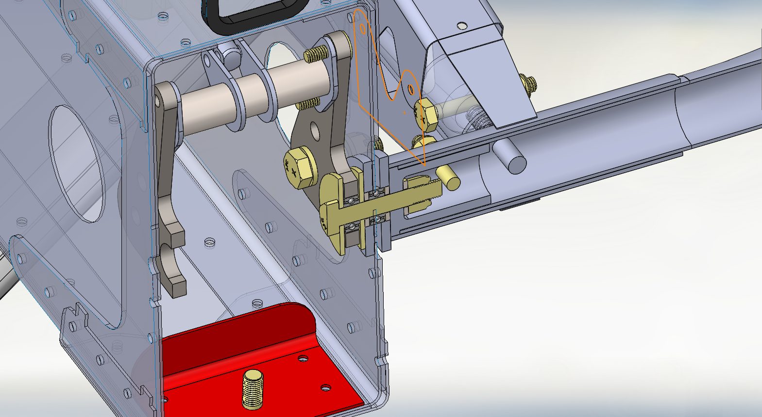
The position of the horizontal stabilizer lift strut allows the leading edge of the stabilizer to raise and lower without change in the geometry of the lift strut. The design of the horizontal stabilizer incorporates the ability to be able to remove the horizontal stabilizer from the airframe for shipment with just 2 additional bolts over the fixed stabilizer design that incorporates folding tail. The optional trim feature will allow the aircraft to be trim throughout its entire CG range. Providing for easy adaptation to different pilot waits and payloads.
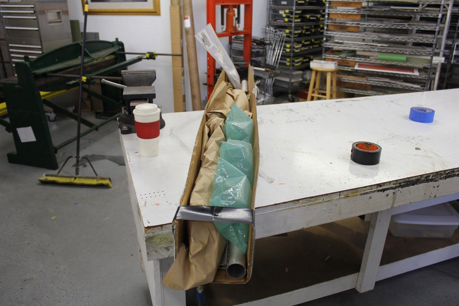
Prepping Rudder Kit for Shipment
We use a loading trough to prepackaged all of the components for the rudder kit assembly. We will then slide the components into the 6 foot long box for shipping.
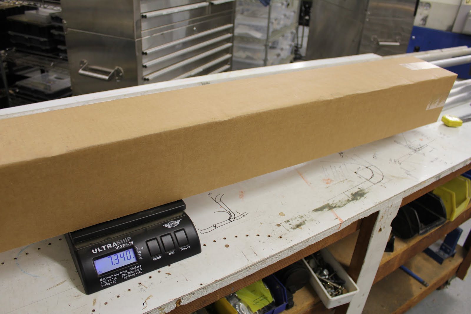
Total weight of the rudder kit ready for shipment weighs 7.34 pounds
February 19, 2016
New Video
Found some old video footage left over from last year’s airshow which was a short time lapse that we took during the setup process. I think the battery died and so we’re only working with about 17 seconds worth of finished video.
February 18, 2016
Rudder assembly kits
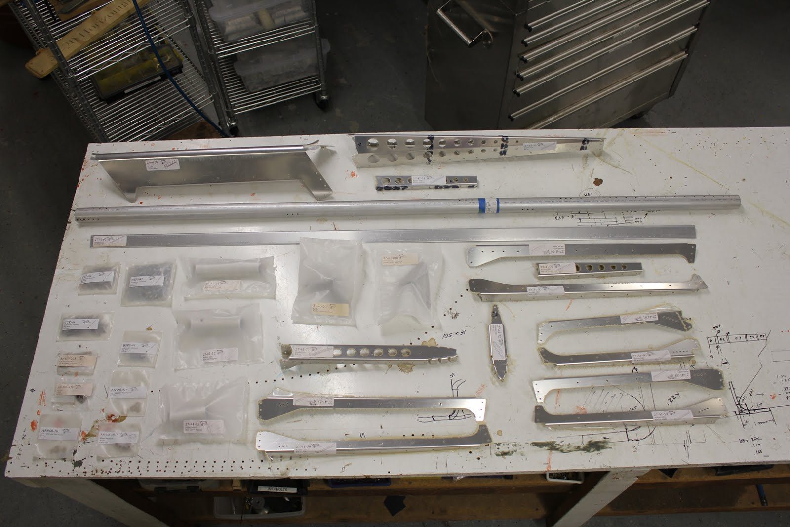
I’m often asked, how do you begin to tackle project of this complexity and size. My answer is always the same. “It’s just like eating an elephant” at first glance it seems to be impossible but if you will simply take one bite every day….. well, you get the picture. Our approach to developing the kit in its entirety is to simply take and work on one part at a time. Then combine those parts in the sub-assemblies. Then build the sub-assemblies into a complete kit. We have been working on the web store and the individual pages within the builders guide. The last couple of days and then quite rainy and cold, so we been working inside. today we are putting together some of the sub-assembly kits, updating the builder databases, updating the web store, and working on inventory and shipping. In order to enhance our builder pages we will be adding a visual picture of the kit contents for each sub-assembly. In the picture below are all of the parts laid out for the rudder assembly kit (LD).
Link to Rudders Assembly Page
February 17, 2016
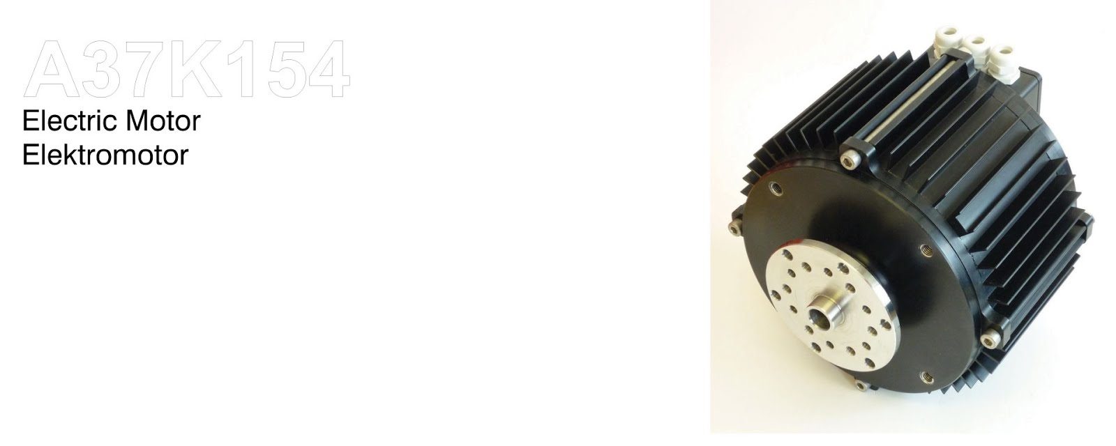
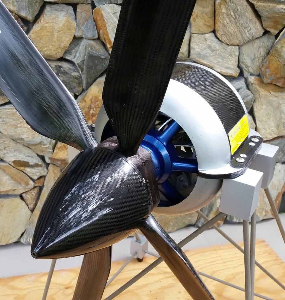
Potential Motor for the EMG-6
A lightweight coaxial air flow cooled permanent magnet synchronous motor designed to directly drive a propeller. Optimized for high continuous torque density and efficiency. With 17 kg of weight (option dependent) it’s capable of supplying up to 30 kW of continuous power at 2000 min-1 providing higher than 93% efficiency. The speed-torque diagram of the A37K154 with a three phase 14Y2 winding configuration is displayed on the bottom figure. The curves are stipulated for different DC bus voltages, without any field weakening applied.
Link to full PDF
February 16, 2016 Fuselage Wing Fairing Progress.
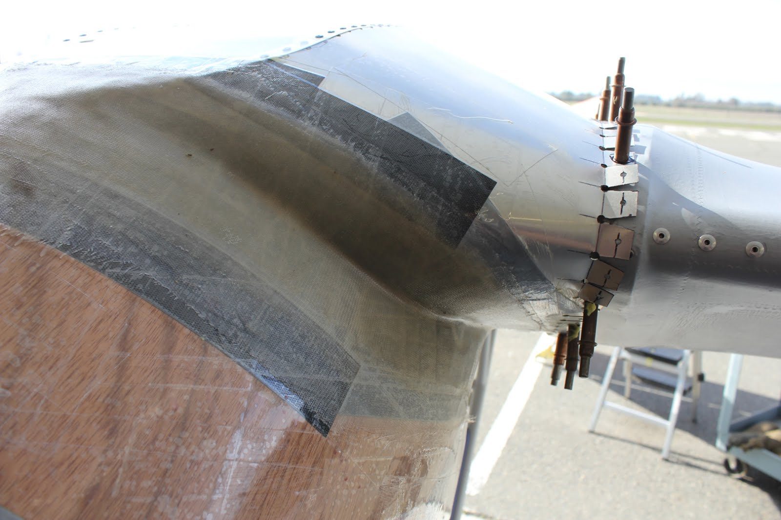
Today we worked on the fairings a bit more. We completed the layups for the fiberglass transition fairing that will interface the front windshield into the upper wing fairing.
Link to the Wing to Fuselage Fairing page.
Aeros/BMW tug trike tow hook system.
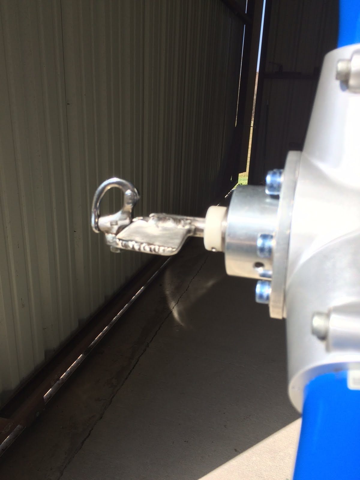
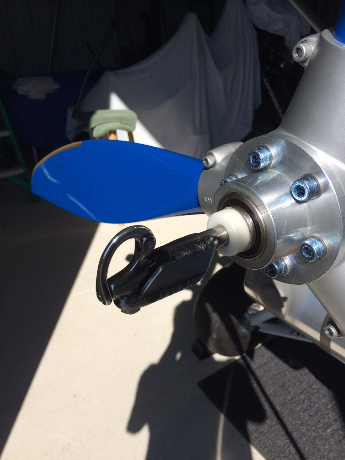
Gregg Ludwig has sent pictures of his total release mechanism that he uses on his Tug. This type of tow system works exceptionally well because the load of the glider aligns exactly with the center-line of thrust on the trike. although those that are not familiar with the system may find it disconcerting to have the towline connected through the prop shaft the system is been in place for many years on many aircraft used for towing.
February 15, 2016 Fuselage Wing Fairing Progress.
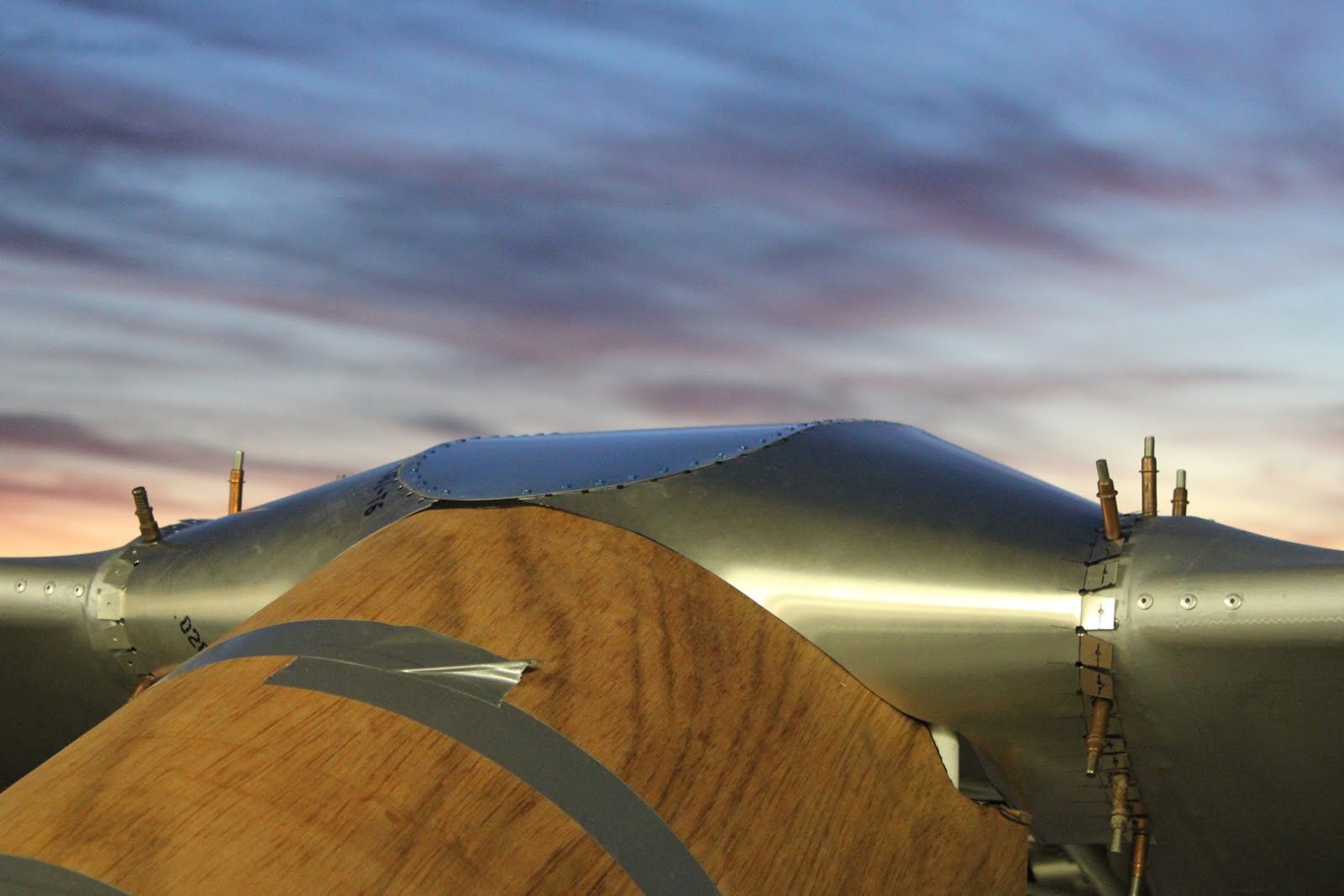
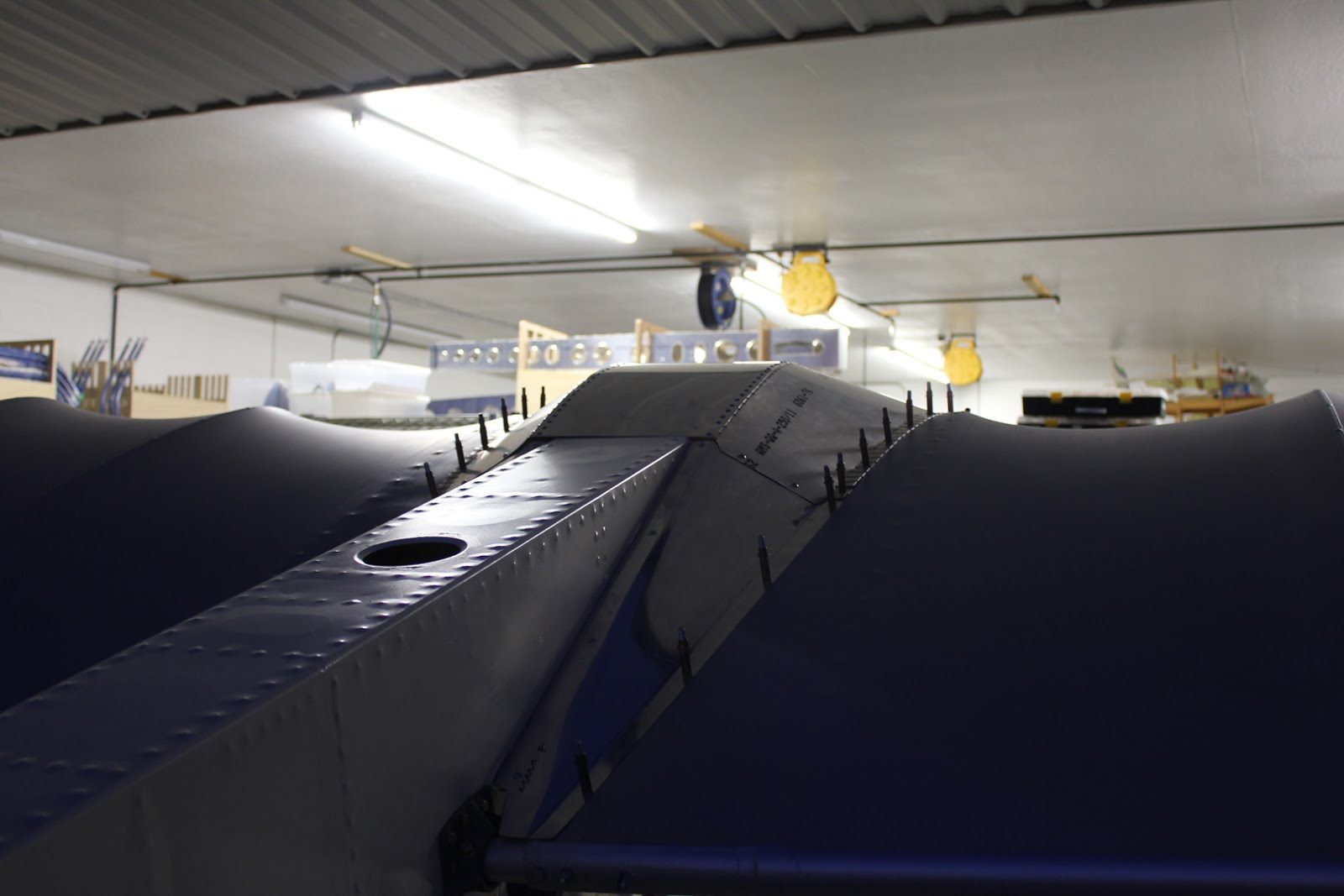
We’re getting closer to completion on the wing fillet fairings that transition the wings to the fuselage, front windscreen, and fuselage boom. we now have the center section wooden block removed and are now all in aluminum.
February 14, 2016 Rudder Assembly Instructions Update
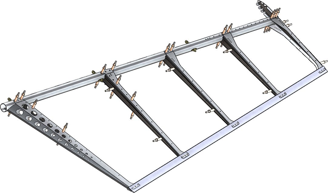
Link to Rudder assembly instructions post.
February 13, 2016
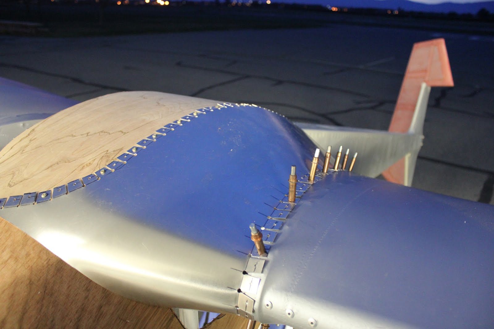
We have been progressing on making the fuselage to wing fairings. We have created an entire post about this process.
Click here to Link to the wing fairing prototyping post.
Pilot Seat Modifications
We are in need of updating the builder files for the seat assembly. Our original design shown in the picture below was designed for the forward seat to be able to pivot forward to allow the passenger easy access to the rear. The original prototype aircraft was designed and built as a part 103 ultralight legal aircraft to be flown as a single place airplane during the first 100 flights using the small Plettenburg Predator 37 sustainer motor. One of the options on the aircraft is to simply weld the pilot seat to the forward bulkhead. And this is how the prototype #1 is currently.
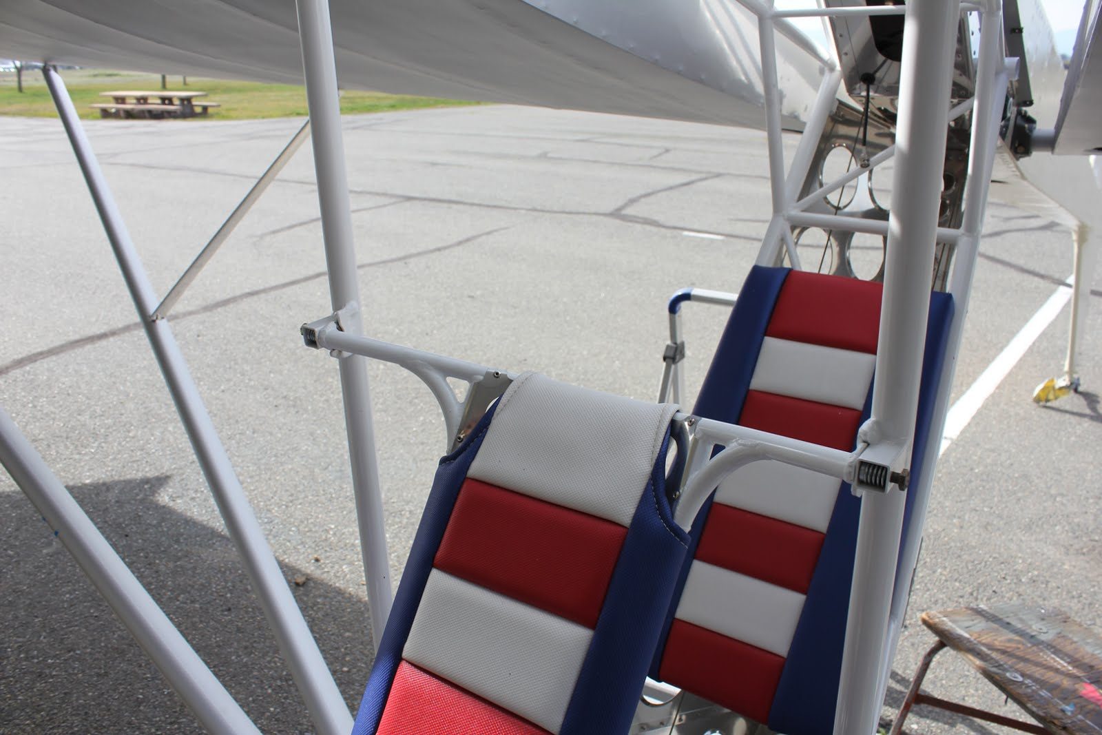
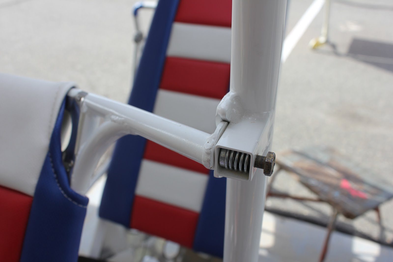
To be able to utilize the second seat either as a pure glider or a limited electric power system it’s more convenient to make the seat detach from the forward bulkhead and pivot forward for easy ingress and egress. Our original design on the prototype #2 aircraft that we showed at AirVenture last year is shown in the picture below. Although this system is very functional it’s stupid looking. originally I had envisioned having a nice CNC machined fitting that adapted into the front of the square tubing to make up the seat release button, but ever since my original design it is bugged me. So were on a quest now to redesign the way that the pilot seat interfaces with the forward bulkhead.
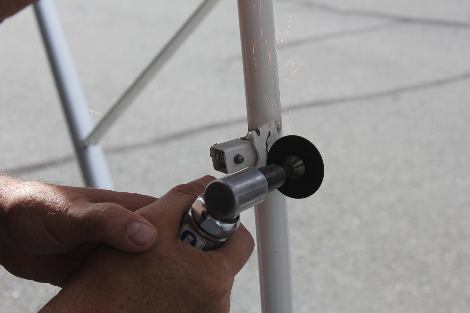
The first step is to cut off the old attachment fittings. in this case we can simply use a air powered die grinder with a cutoff wheel and start cutting away. You need to make sure that you don’t cut into the base material of the forward bulkhead.
Take it slow and steady and just begin cutting away the biggest chunks to be able to have access to the rest of the material.
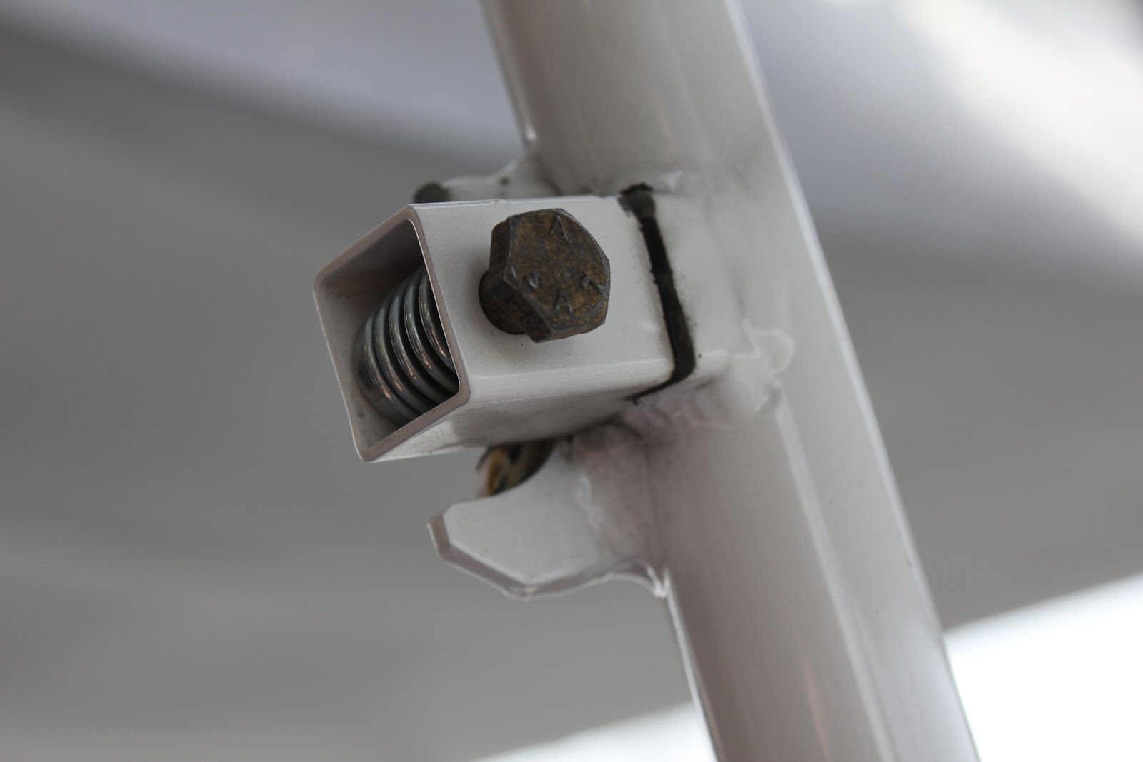
Once you got the big chunks cutaway night can start working on the smaller portions of 4130 that remain. One of the great joys of working with 4130 steel frames is that it’s virtually impossible to screw up anything that can’t be fixed. When making modifications like this it makes for a very user-friendly medium to work in.
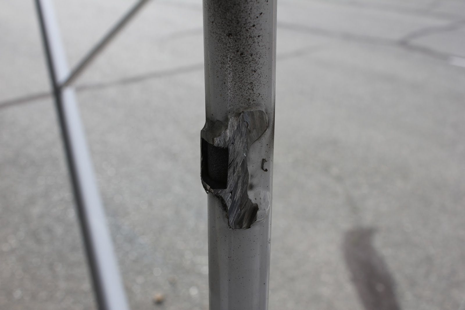
Once we get down fairly close to the base material we can take a file and start knocking off the high points. On this frame it’s been powder coated which makes it a pain but nonetheless still very doable.
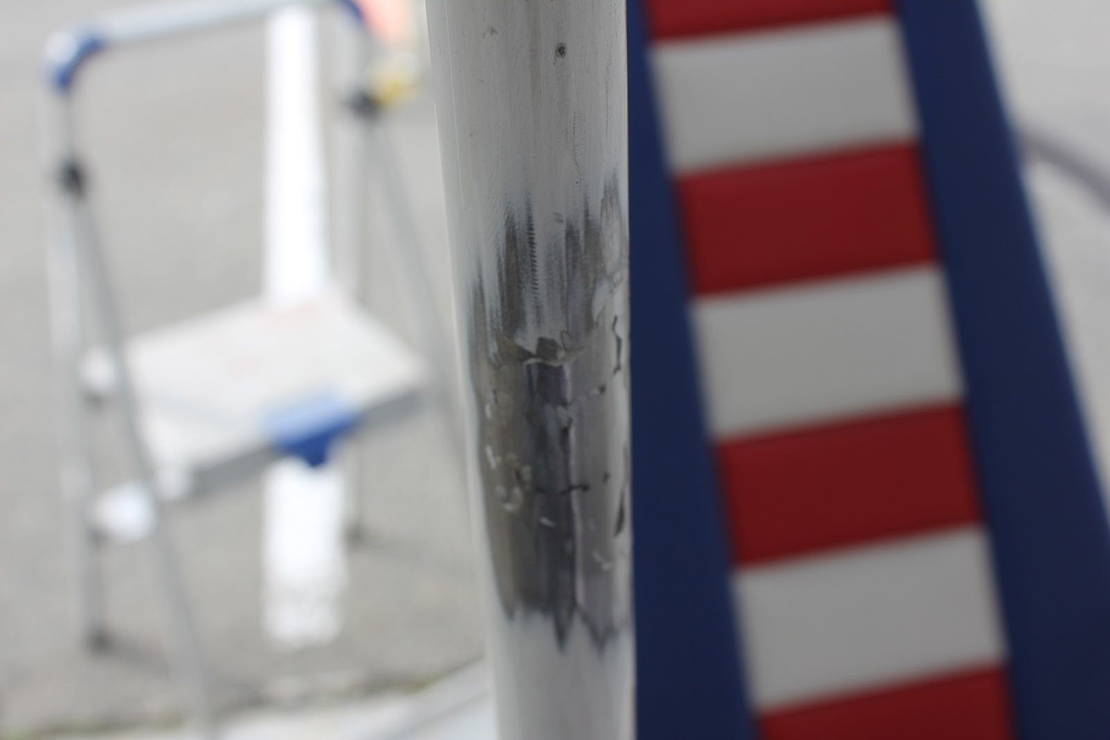
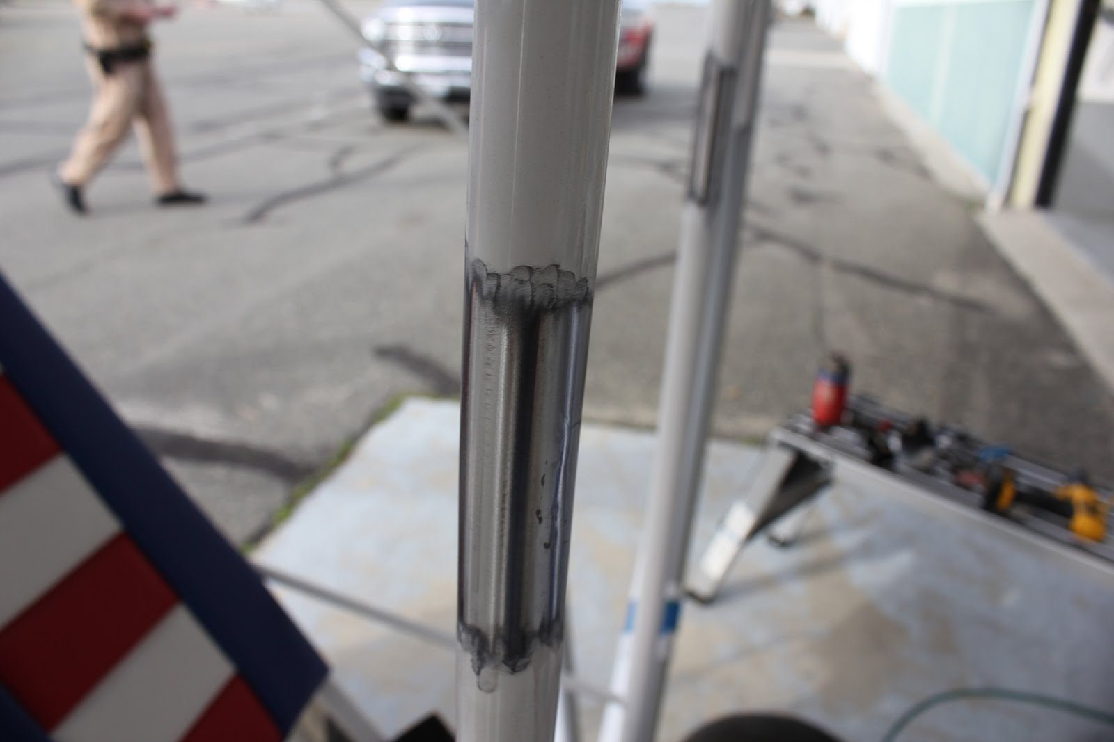
Next step is to switch out to a Scotch Brite wheel on the die grinder and burnish away the remaining powder coat and the roughness around the area where you remove the welded component. We’re now ready to start any modifications to the structure.
Front Windshield Prototyping Begins.
we’ve begun the process of laying out and prototyping the front windshield. We are creating a separate post that will follow this process from the beginning to the end. Click here to visit the windshield prototyping post
February 12, 2016 New Electric Motor
One of the other motor options that were looking at is this motor that is designed by Donald Lineback. In the next couple of weeks we should have more information on the details of the motor.
February 11, 2016 Continue Progress on Prototype #2
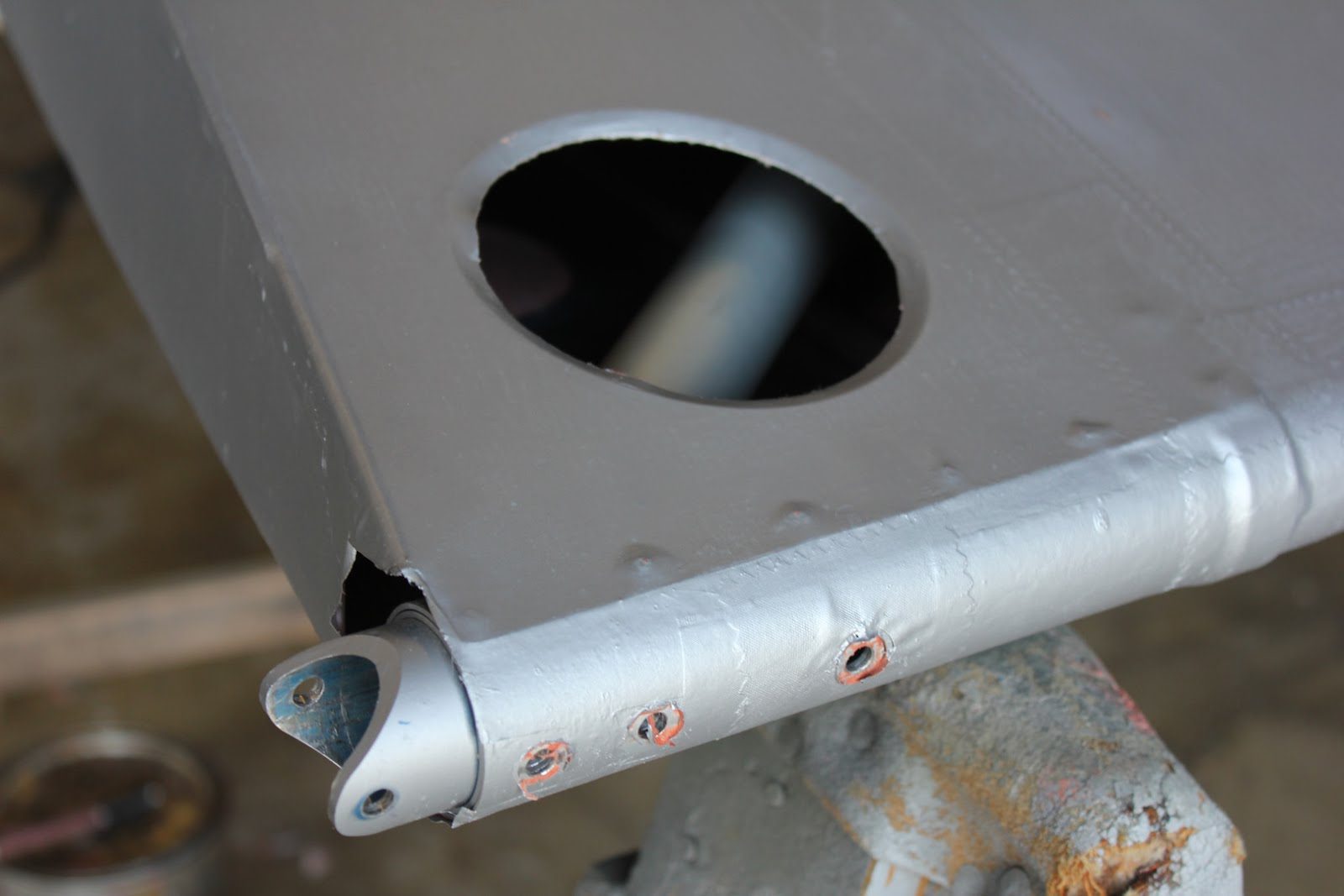
Today’s work involves replacing the components for the wing attach system. In this picture here we see the old spar fitting for the rear spar being removed.
In yesterday’s work we finished up on putting the right wing onto the aircraft.
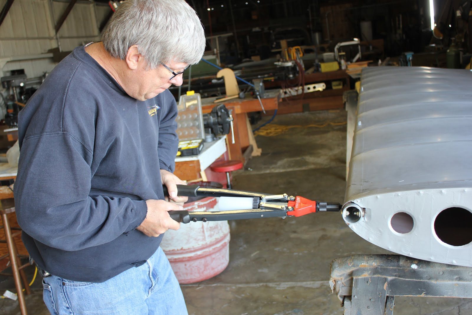
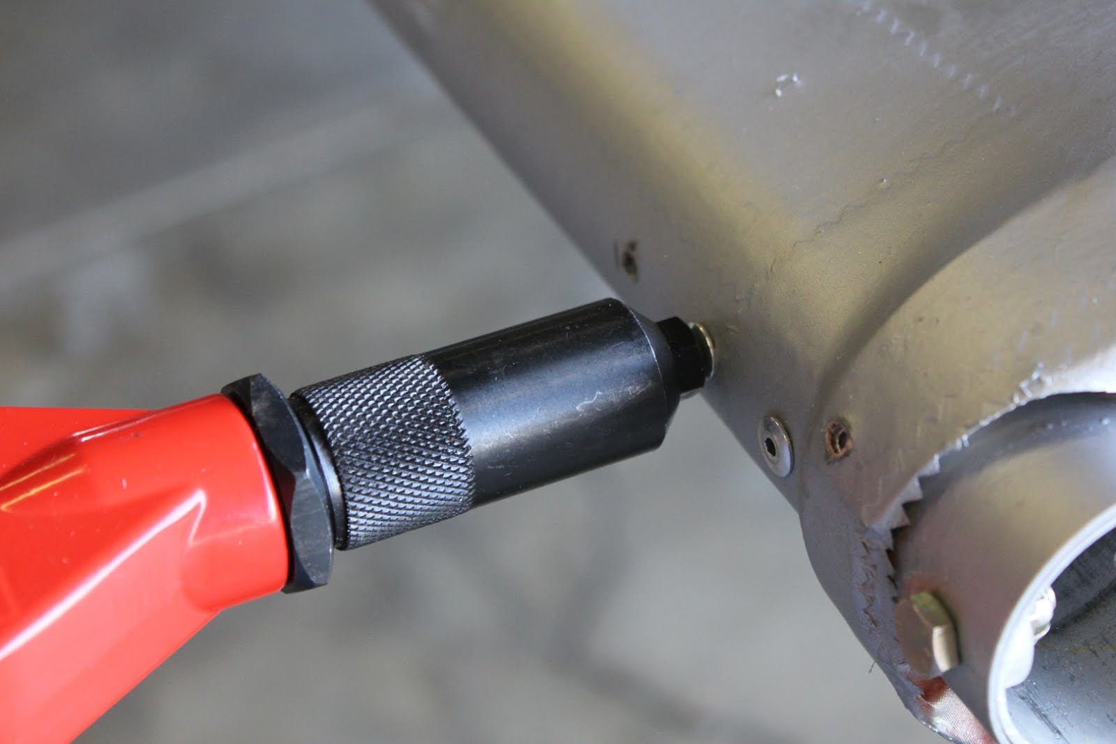
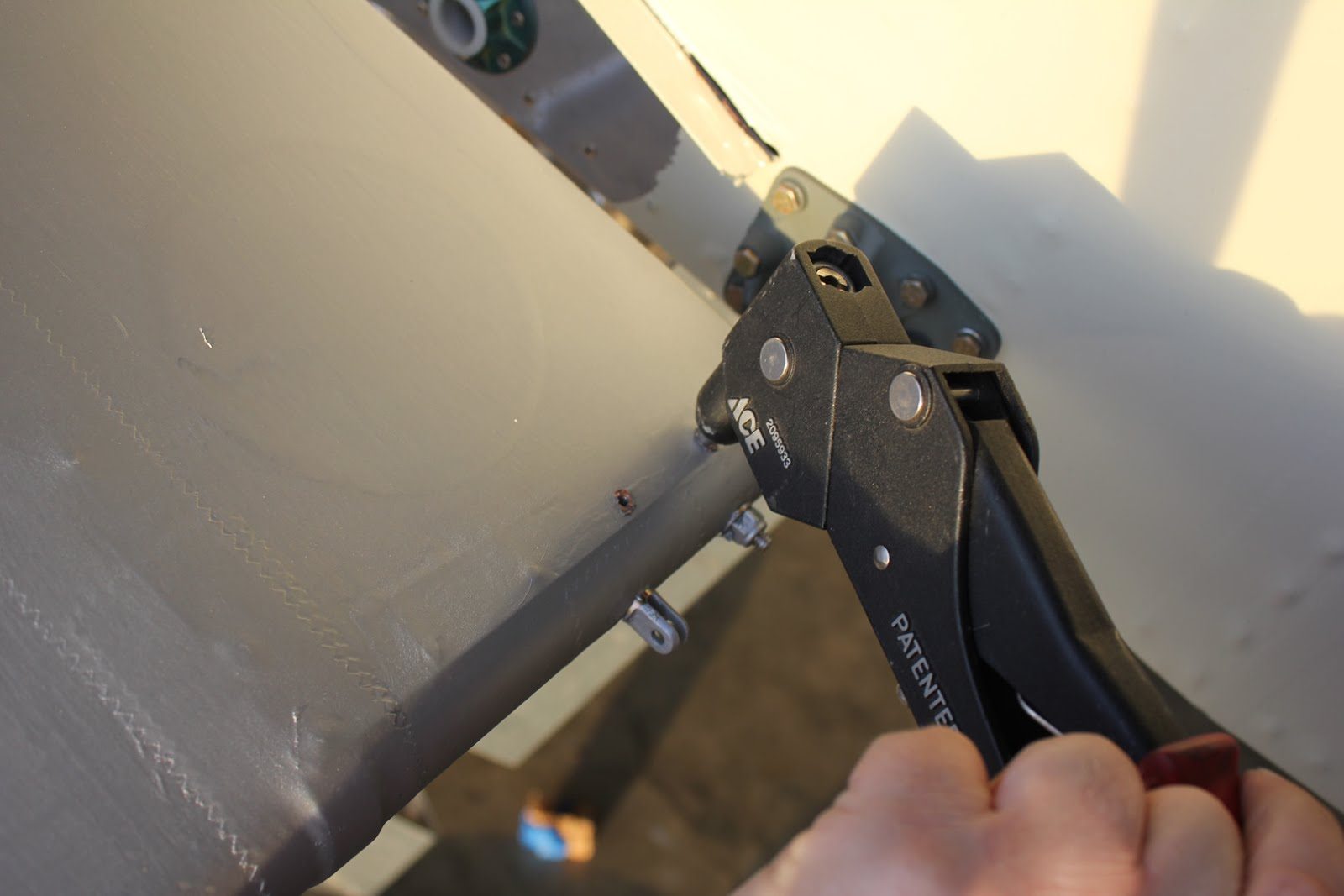
The forward spar reinforcing straps get riveted in place with (3) 3/16 aluminum pop rivets. these can be pulled pretty easily with a standard pop rivet gun but we happen to have the larger size rivet head on this one so was easier just to grab the larger rivet puller.
A close-up view of the pop rivets holding the forward spar wing fold straps in place.
The replacement rear spar adapter bolted in place. And were now ready for installing the wing.
Once the wing is been installed and we verified the fit of both the forward and rear spar adapter fittings we can now pop rivet the top inboard skin back to the wing spar.
With both wings installed and a verification of proper rigging we can now begin the process of replacing all of the temporary bolts holding the wings on and the wing struts with the proper sized permanent bolts.
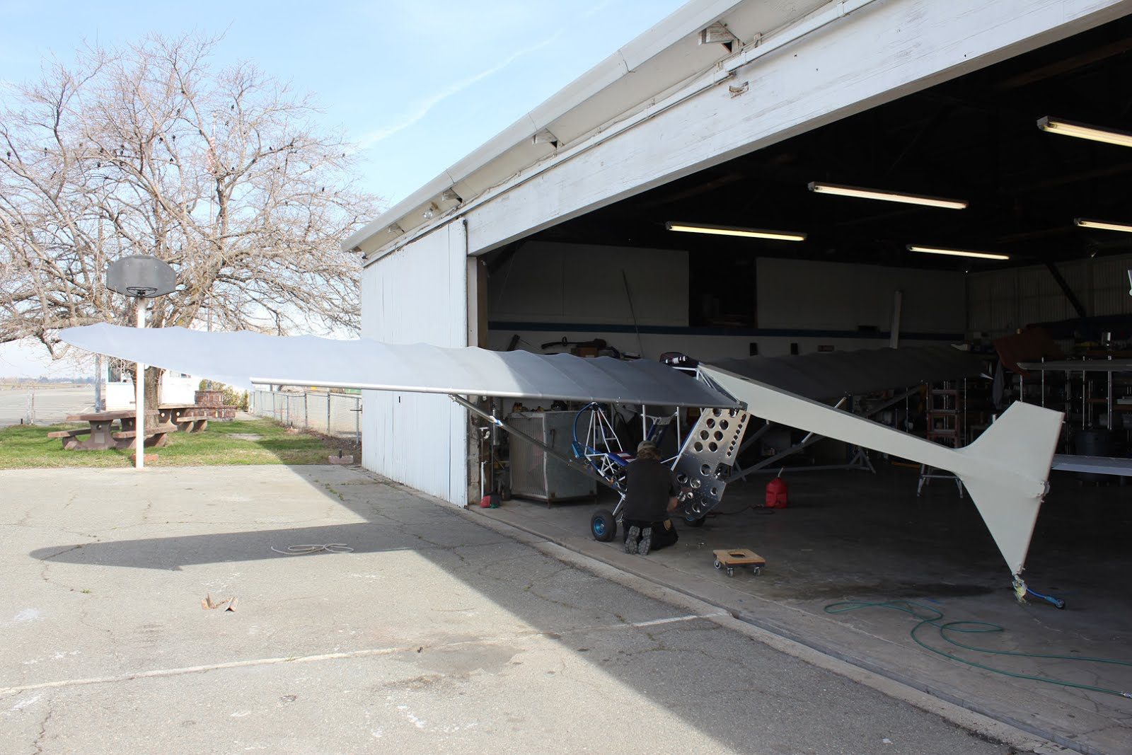
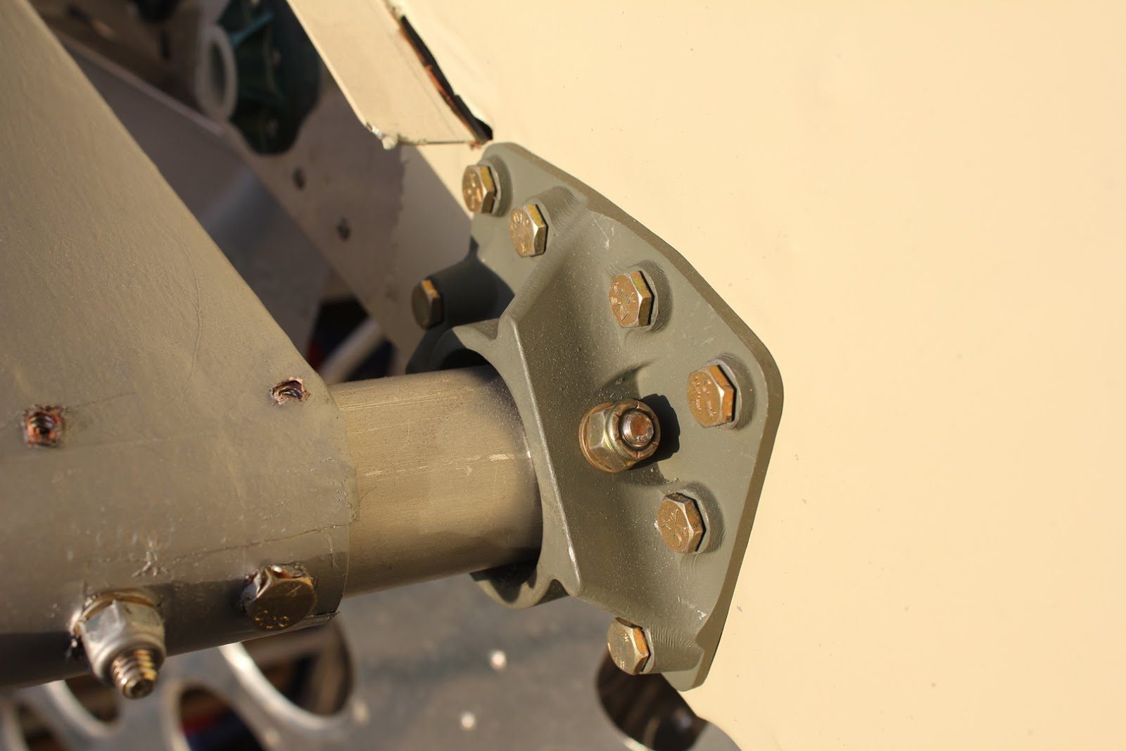
A close-up of the rear spar attachment engaged into the fitting on the fuselage boom. the attachment bolt is purposely put in from the bottom side which will provide easier access and avoid having to remove one of the 3/16 bolts on the top side of the fitting. So make it much easier for installation and removal of the wings.
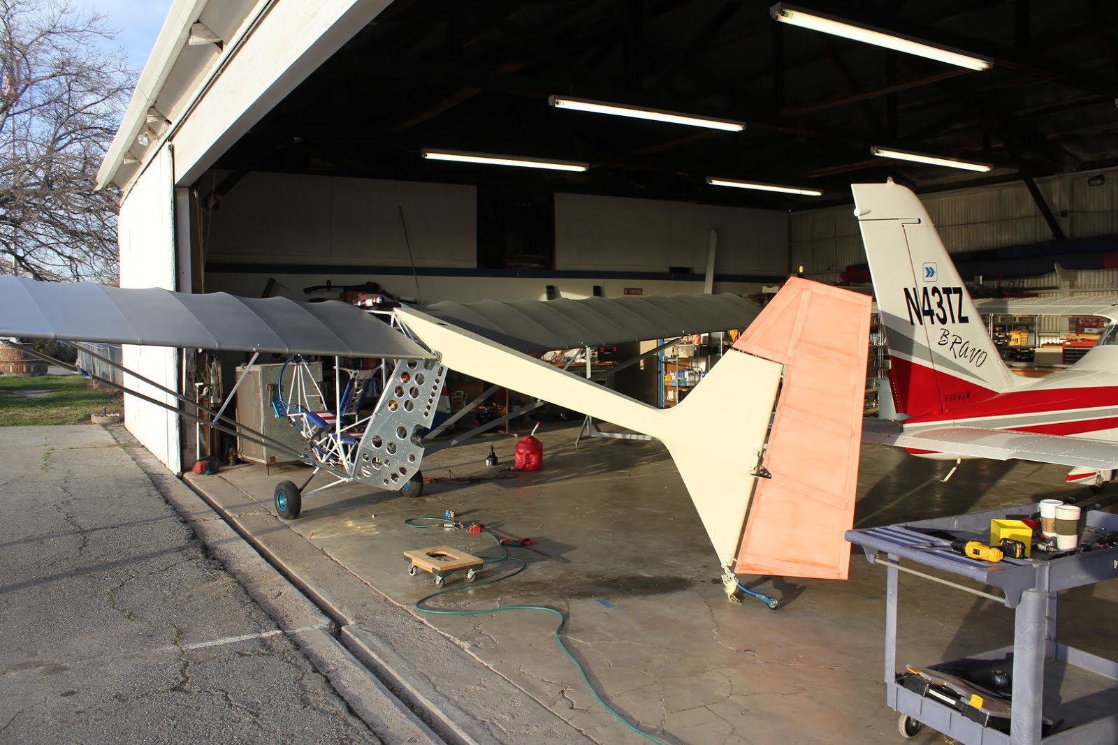
time to reinstall the (LD) rudder after the covering process has been complete. Although be more convenient to finish the painting process off of the aircraft on individual components. I have been pushing to get the airplane into a flying condition and solve any of the unresolved problems with the differences in the #2 prototype. Fortunately the poly fiber system is pretty user-friendly and even painting it while it’s on the airframe is pretty easy to accomplish.
With the wings now installed I can begin the process of designing the center section fairings that integrate with the windshield. The prototype will be a one-off design until we prove the concept.
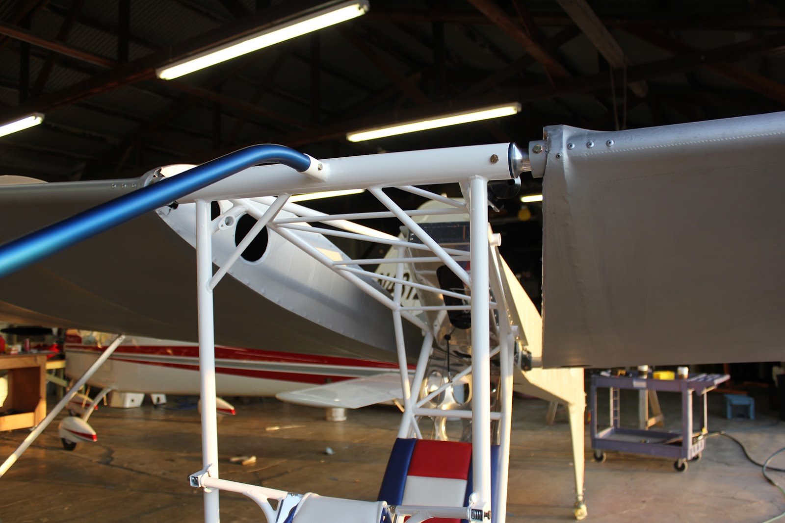
We have removed the parachute and the parachute rocket motor from the center section so that we can start the work of building the upper fairing and windshield transition.
New File Updates
Every day we are putting effort into creating new links to the builders database and propagating the information accessible only to the paid builders over to the new website format. In the long run this is going to be a very useful and user-friendly system. Right now were still in the updating process and its going to get much better as time goes on.
Most of the new updated posts that are being applied to the website are postdated February 1 so that they don’t show up at the top of all the blog posts. additionally all of the new blog posts and links can be found going through the “Building the EMG-6” Tab.
February 10, 2016 Wing Installation and new posts
57-10-06 Rear Spar Attach Plate
57-10-08 Wing Fold Strap
57-10-09 Wing Fold Fitting
57-10-25 Fuselage to Rear Spar Adapter
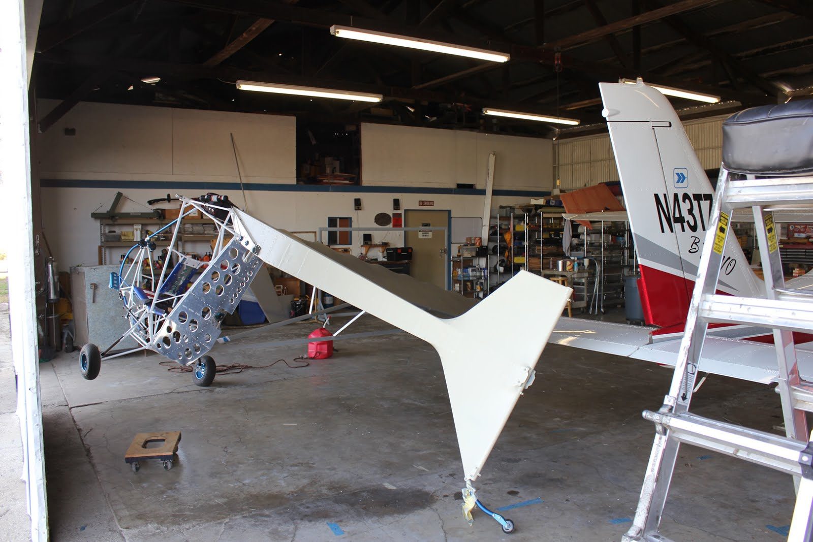
We have finished up the modifications for the wing attach fittings. As a result we brought the fuselage down to the big hangar so that we can install the wings and trial fit the new updated fittings.
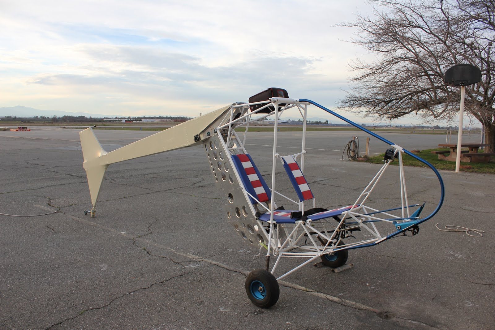
Because the fuselage frame is so lightweight and there’s not any motor or even flight controls on the frame we will need to use a ladder to hold the wing in position during the installation process.
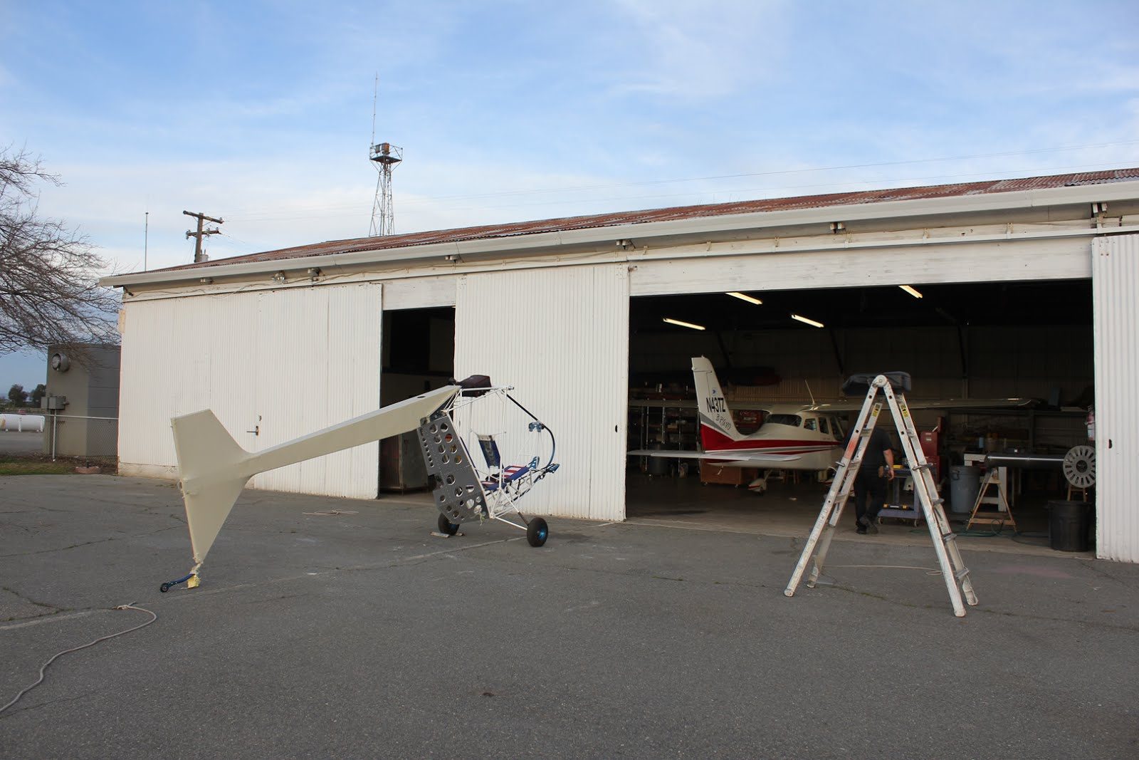
Installing the wings is a simple lives placing the wing tip on the padded ladder and then slide a bolt through the forward fitting and slide a bolt through the aft fitting.
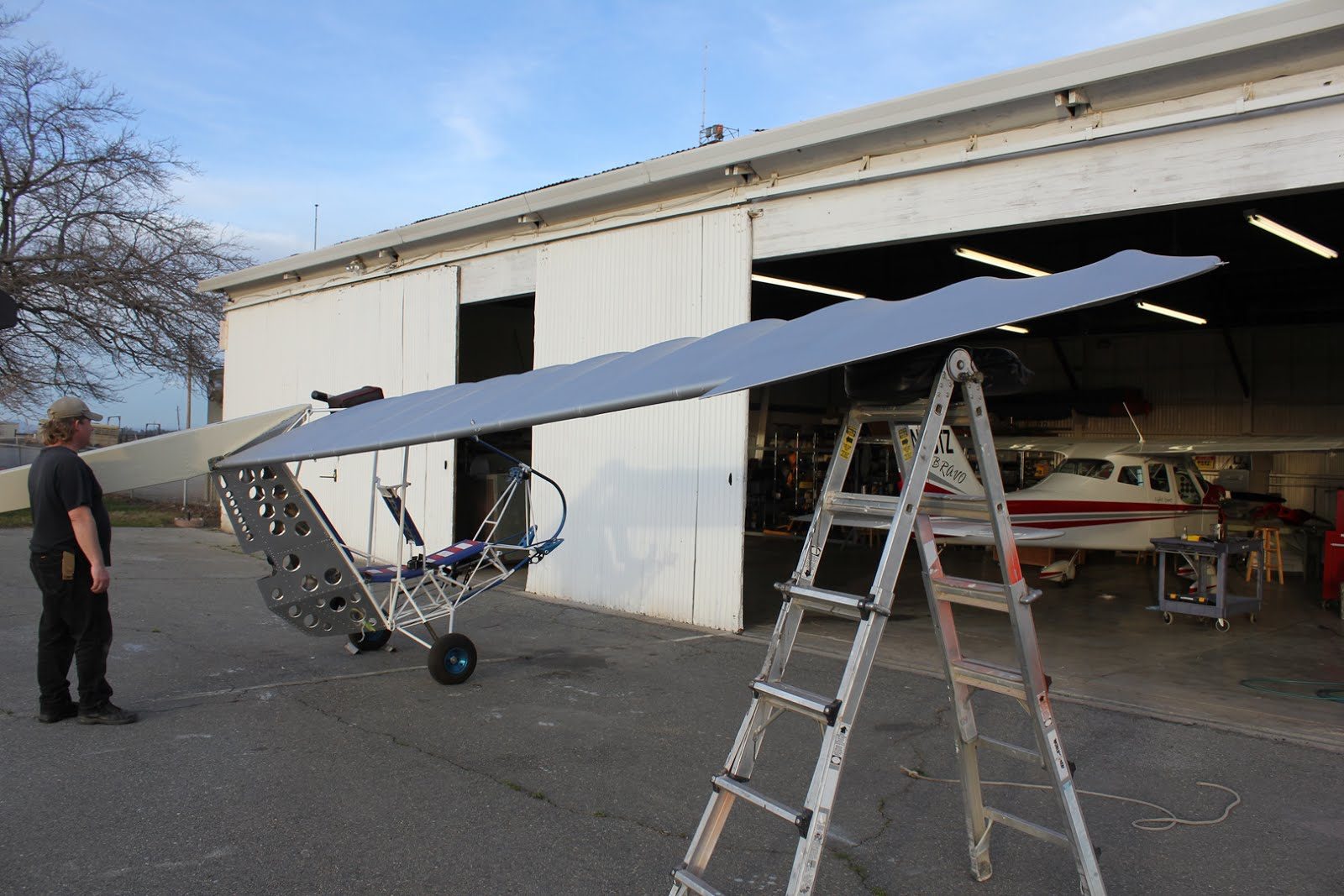
The new forward wing spar attach fittings now shown in context.
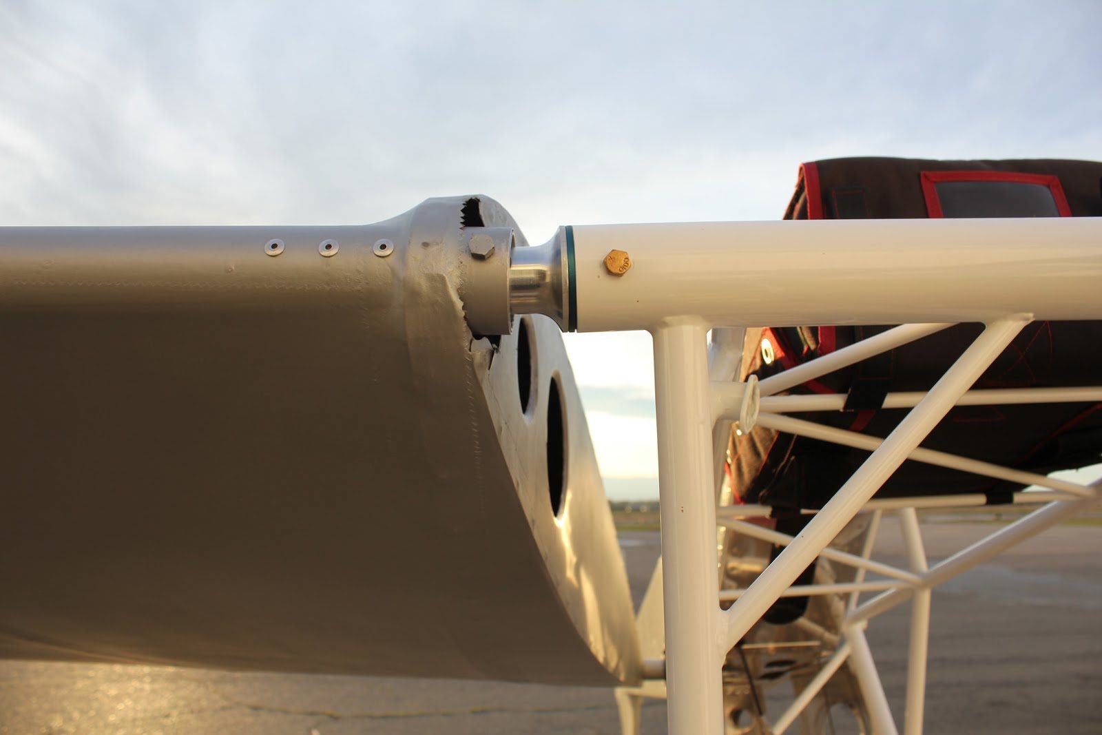
And the new rear spar attach fitting. all of the bolts are just temporary bolts while we trial fit and check our geometry. I don’t know if you can appreciate the complexity of manufacturing all of these parts individually off of the airframe, then bolting them altogether and having both the forward wing spar fitting and the rear wing spar fit and perfectly align. The maximum clearance and adjustment on the forward spar fitting is .032″. all of this has to occur while maintaining 3° of dihedral and 3° of wing sweep. Thank God for Solid Works!
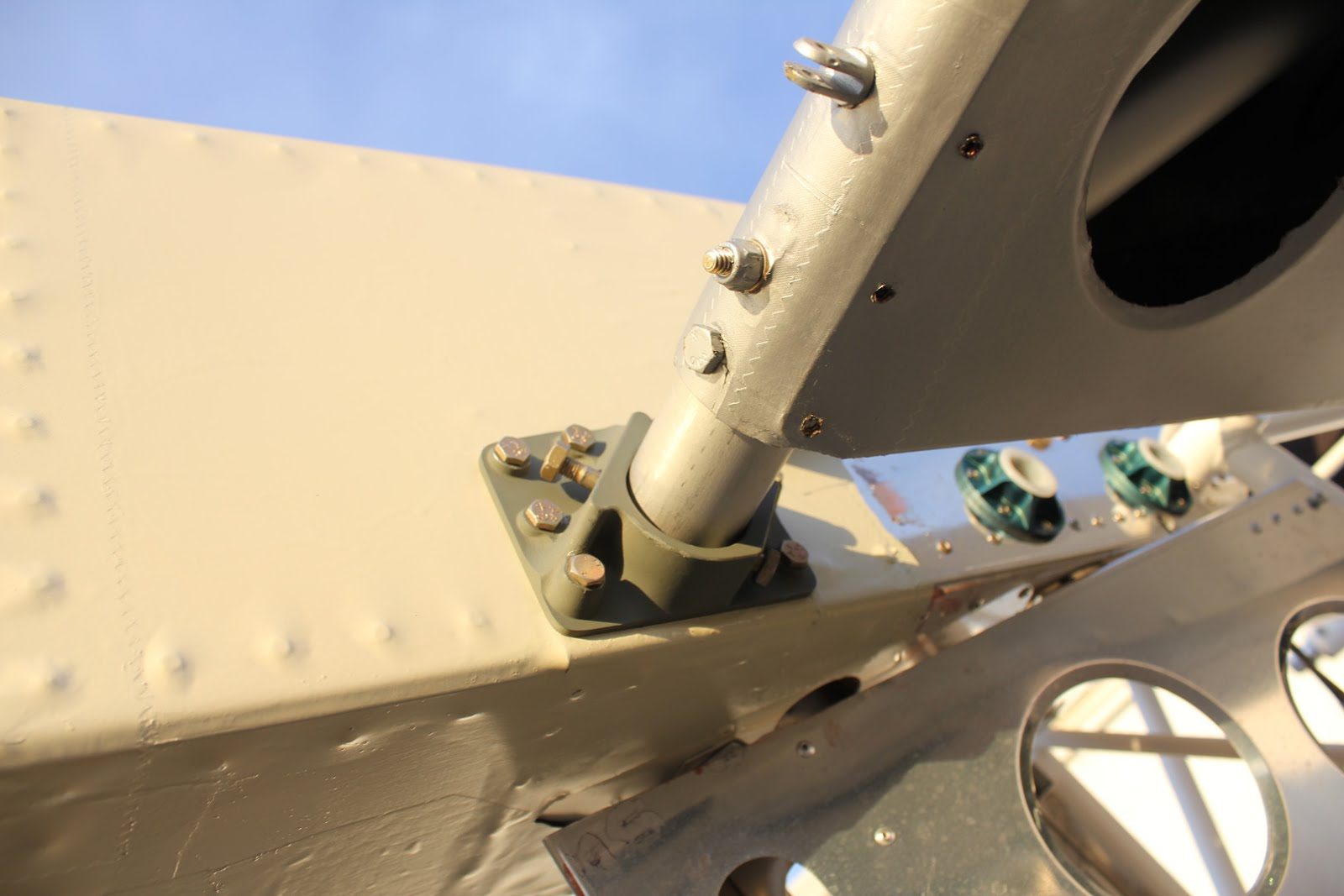
once the wing is installed onto the aircraft and resting on the ladder. We have to go find the wing struts.
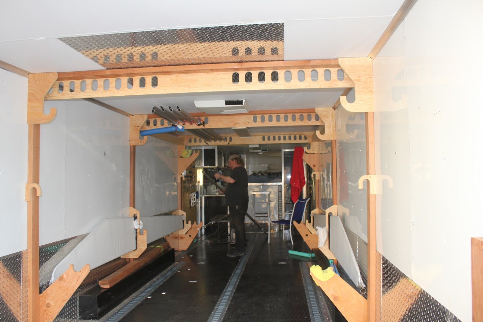
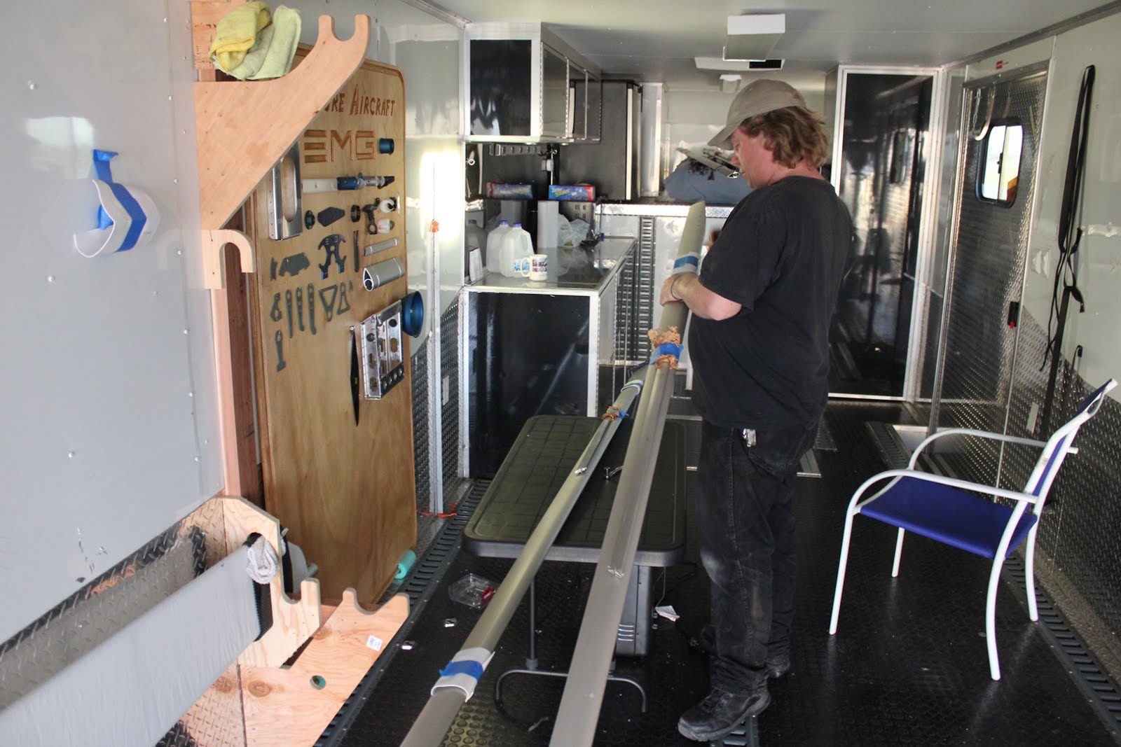
Found the wing struts. They were still in the trailer left over from the air venture airshow last September. We have been working on so many other parts of the project that we have not reassembled the airplane since the airshow. The trailer is set up with slots to be able to carry up to 3 airplanes worth of wing struts. Even though it doesn’t look like it we can manage to fit 3 airframes into the trailer.
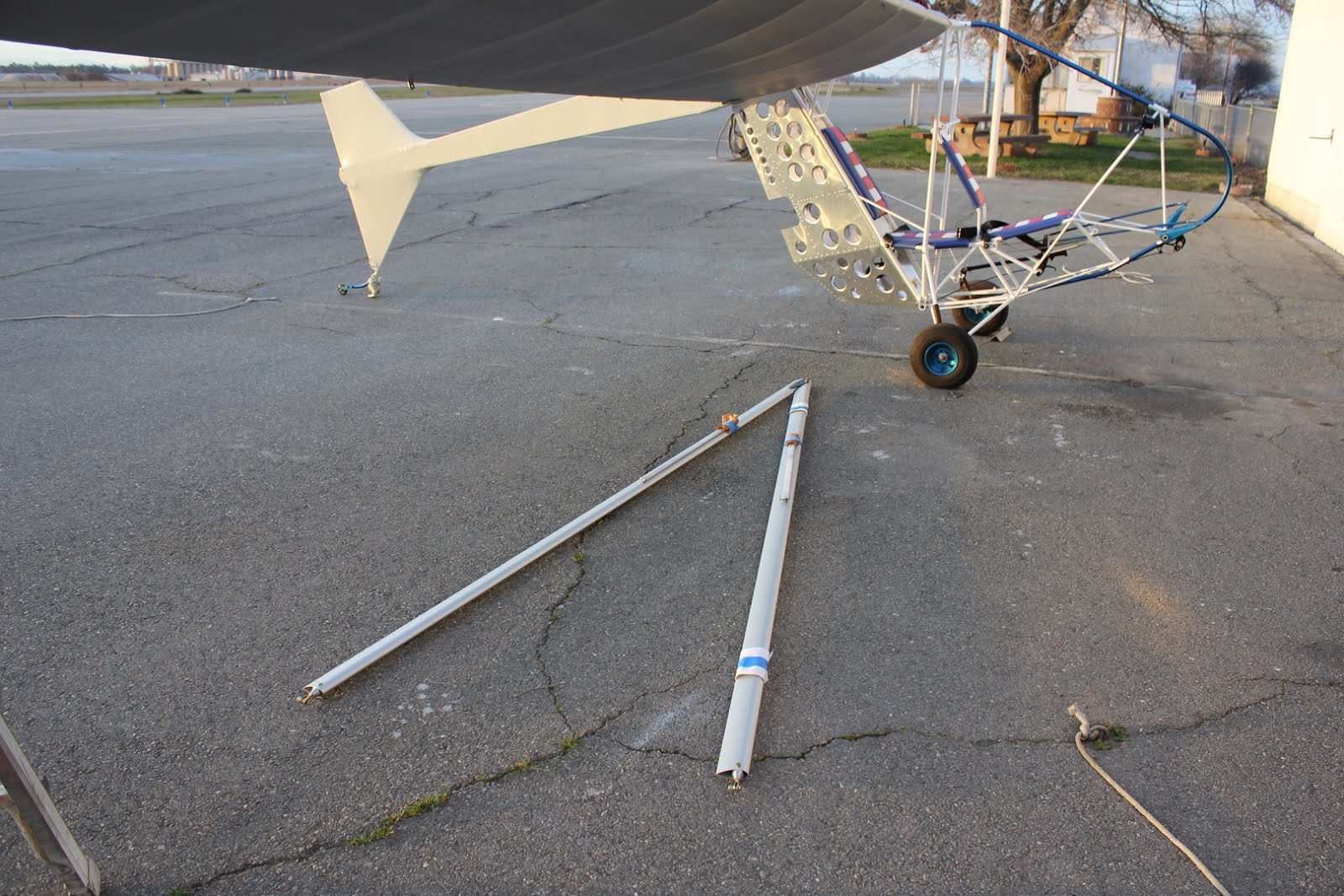
The wing struts reassemble fairly quickly. 2 AN4 bolts that tie the 2 struts together.
After the struts are bolted together and ready for installation
Installing the wing struts is a one-man job with a little creativity, or really simple with 2 guys working on it.
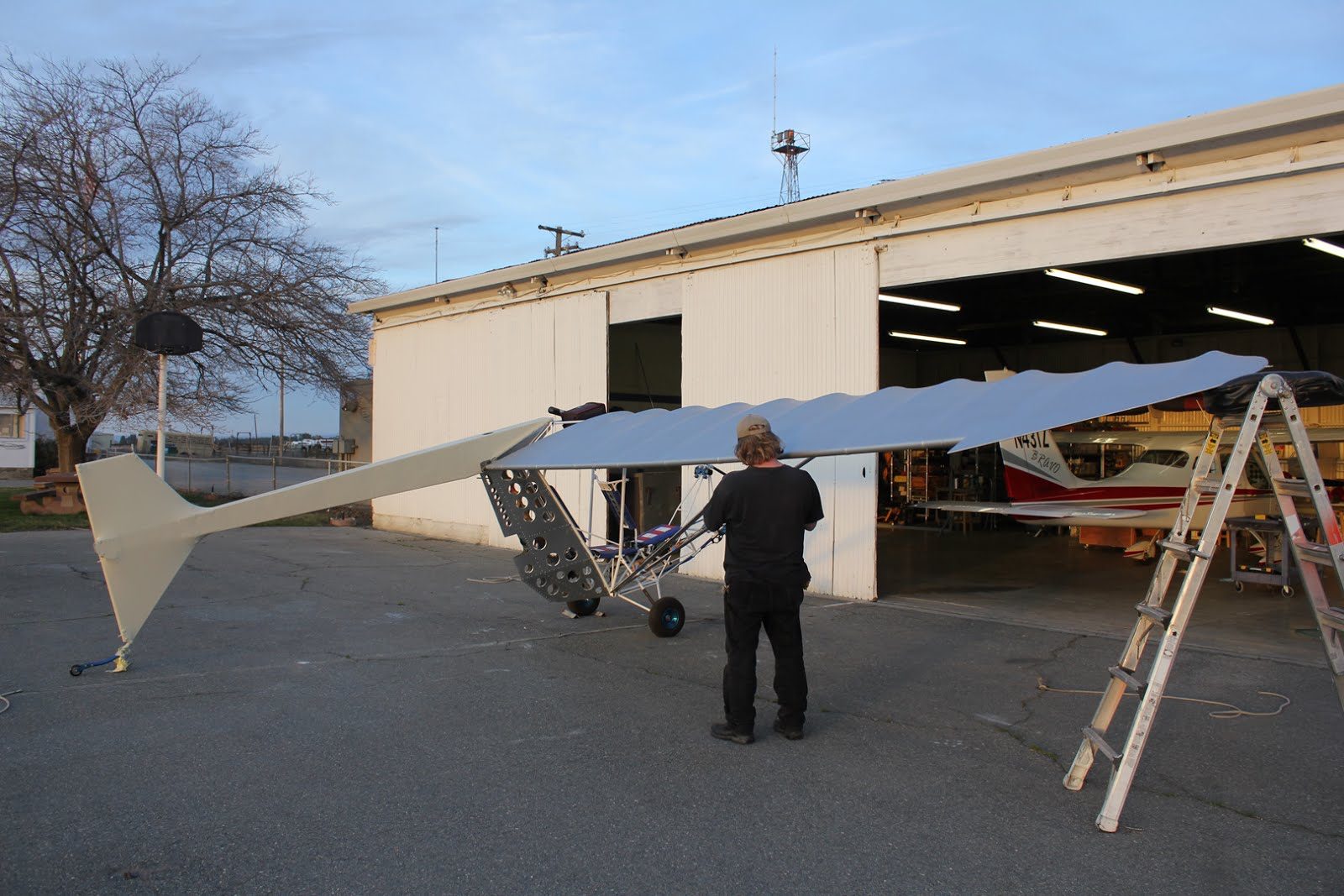
The wing struts will be installed temporarily until we’ve determined that there’s no other modifications that we wish to make to the new wing attach design.
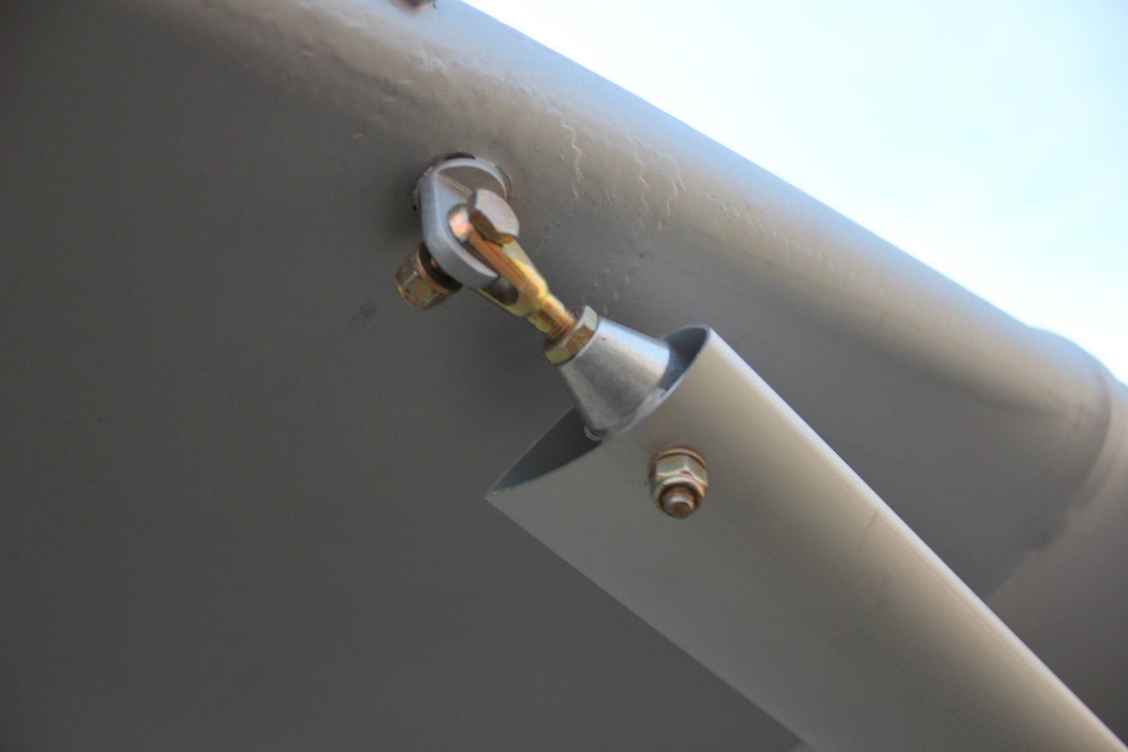
Once the struts are in place with their 3 bolts the jury struts have quick release pins that simply pop in place.
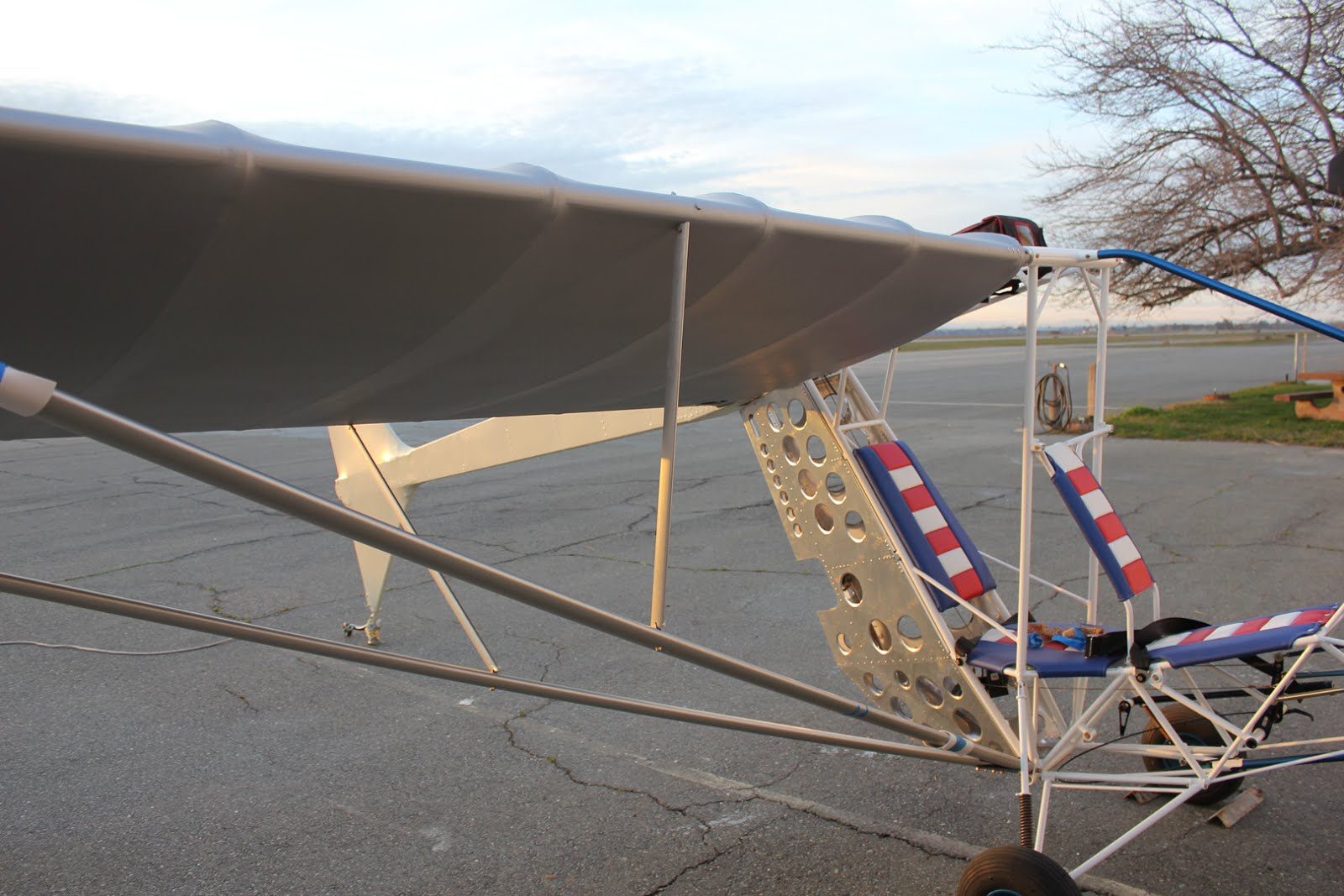
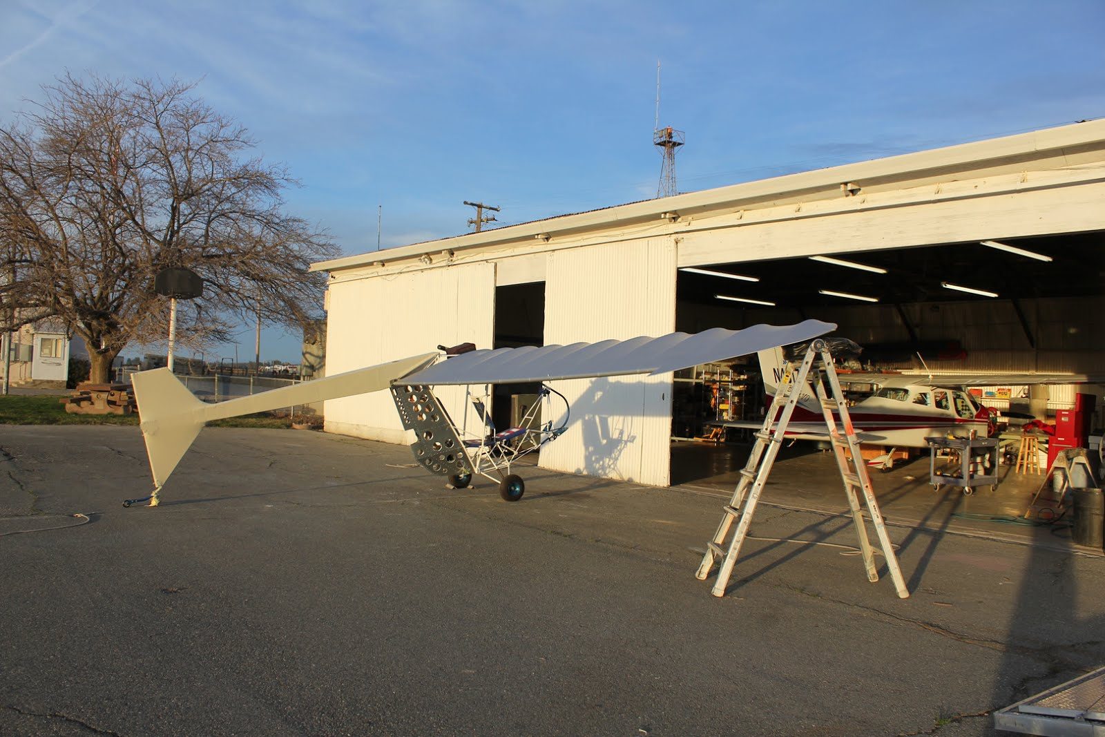
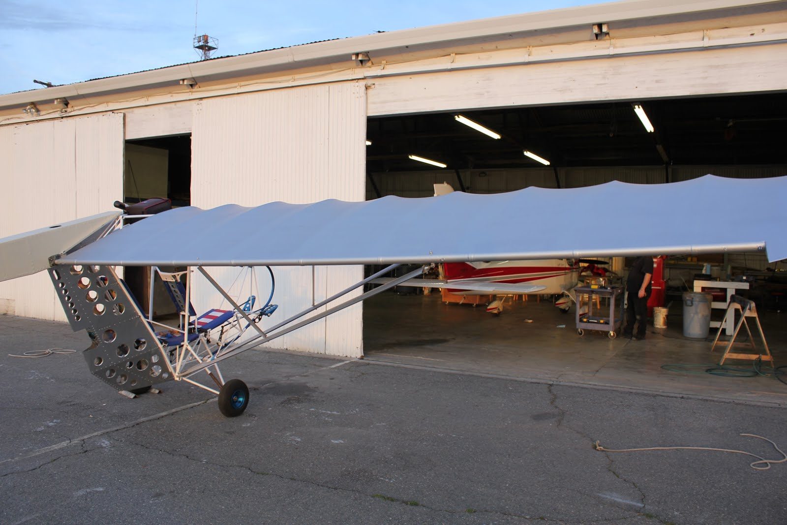
The right wing installed, and ready for the left wing.
February 10, 2016 Rear Spar Attach Plate
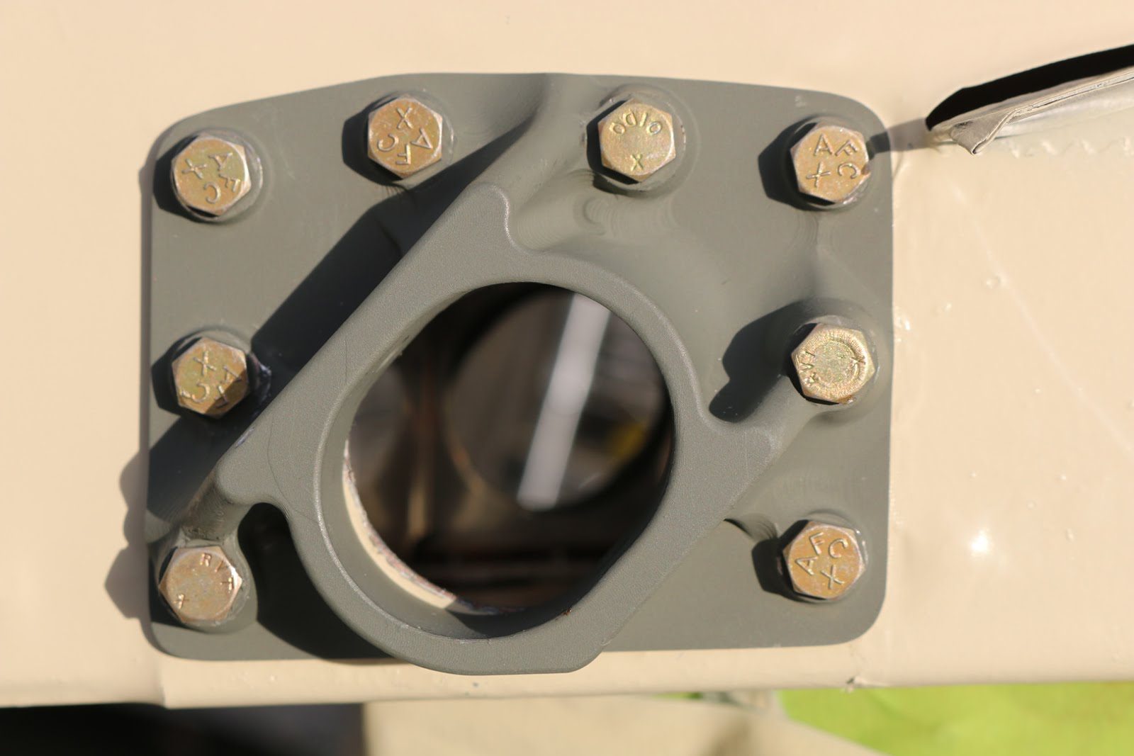
We have completed the installation process for the rear spar attach plate on both sides of the fuselage boom. We have also completed the installation page accessible through the Tab on the home page labeled “Building the EMG-6” “Wings” “Wing Assembly” ” 57-10-06 Rear Spar Attach Plate”
Quick link to (57-10-06 Rear Spar Attach Plate) page, click here
Quick link to (57-10-09 Wing Fold Fitting) page, click here
We’ve also added the installation page for the forward wing spar wing fold fitting that pivots and articulates during the wing folding process.
February 9, 2016 Progress Continues on Prototype #2
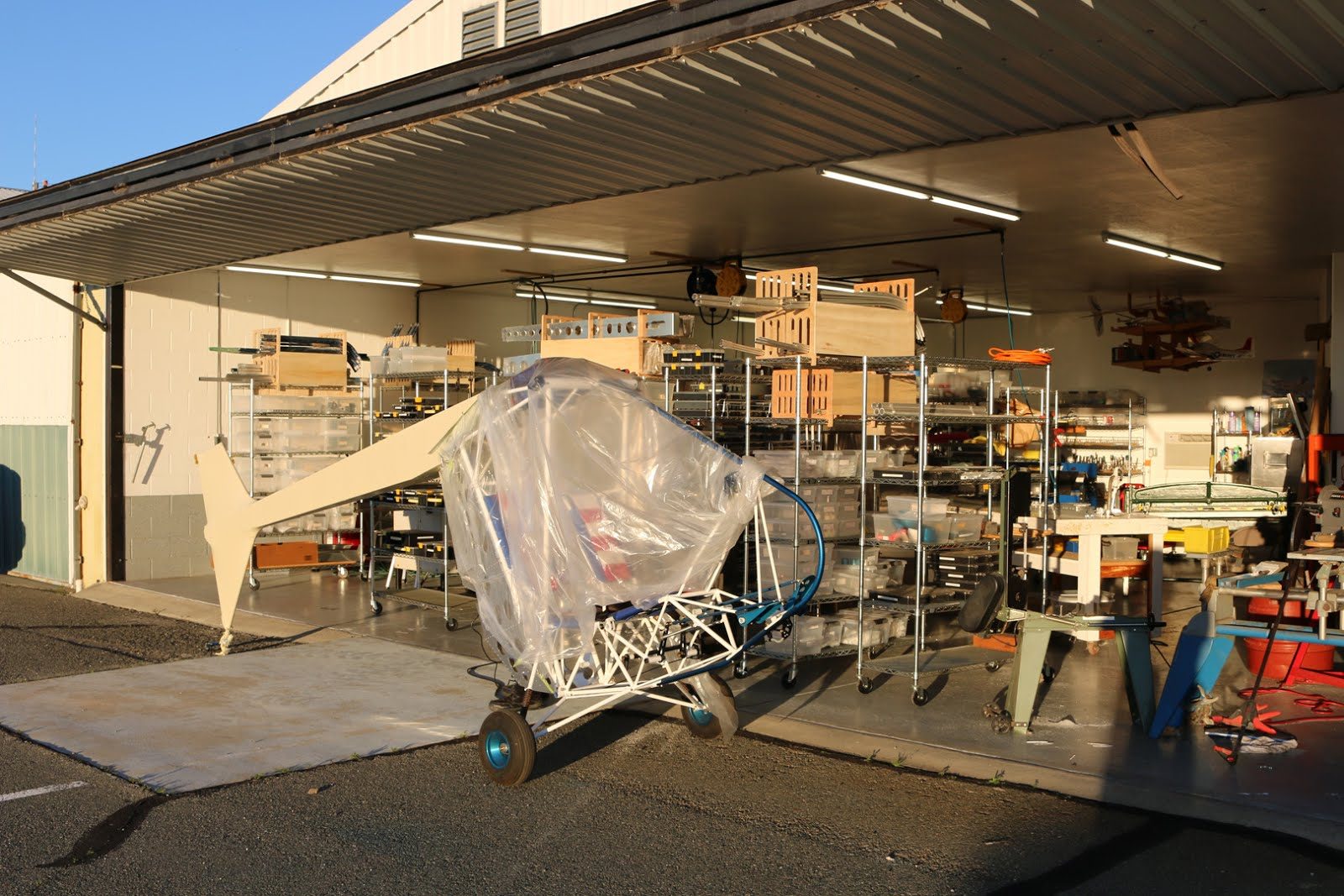
We finally have a little springlike weather which is more normal for California this time year.
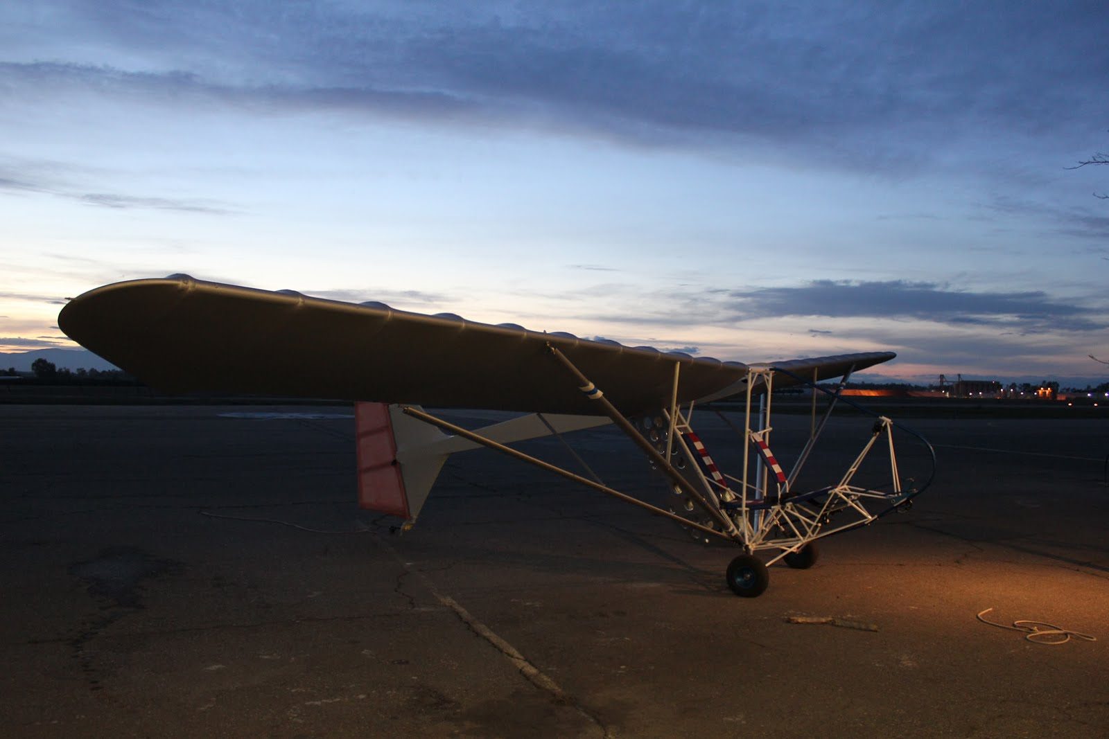
We still have the prototype covered with plastic from the painting that we were doing on the fuselage boom assembly and vertical stabilizer.
Hanger 7 is our prototyping Hanger and is where all of the machining and development take place.
We used to have some room to be able to bring an airplane inside but that was many months ago since we were in that situation.
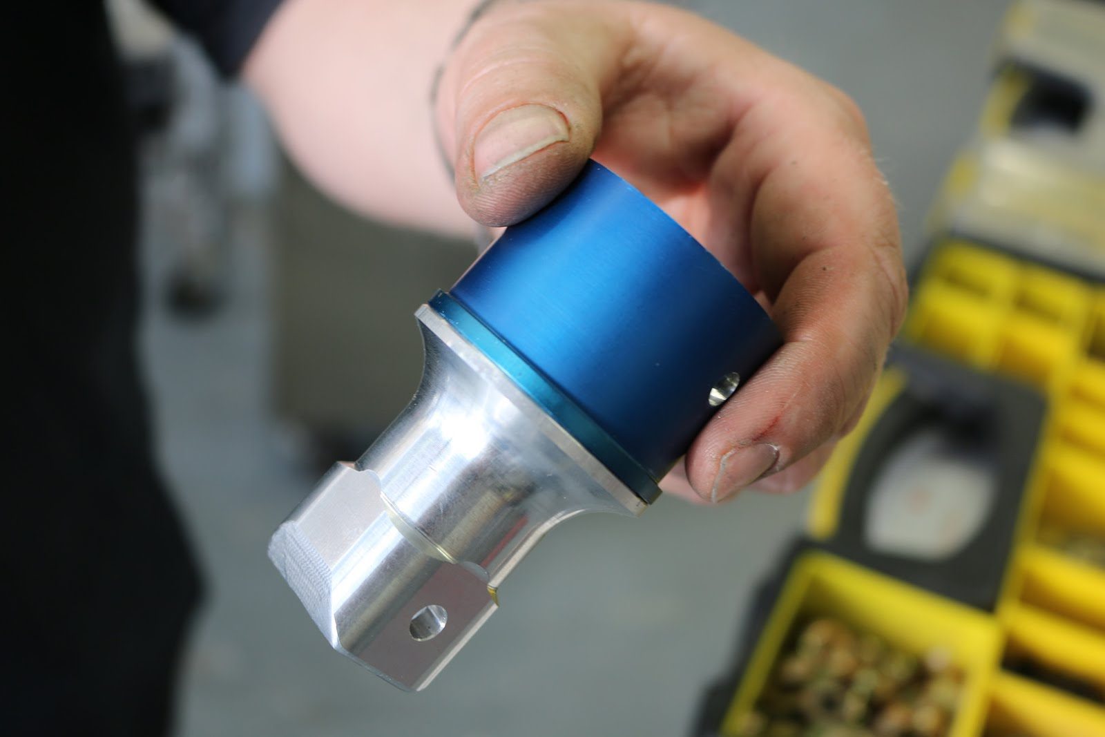
We are conducting the modifications to the rear spar wing attach fitting. This is the new design that changes the configuration from a channel bracket to a custom built attachment fitting.
The new design is much cleaner, A little stronger, and slightly heavier than the old design.
The two designs are designed to be used interchangeably and this is a optional modification to the aircraft.
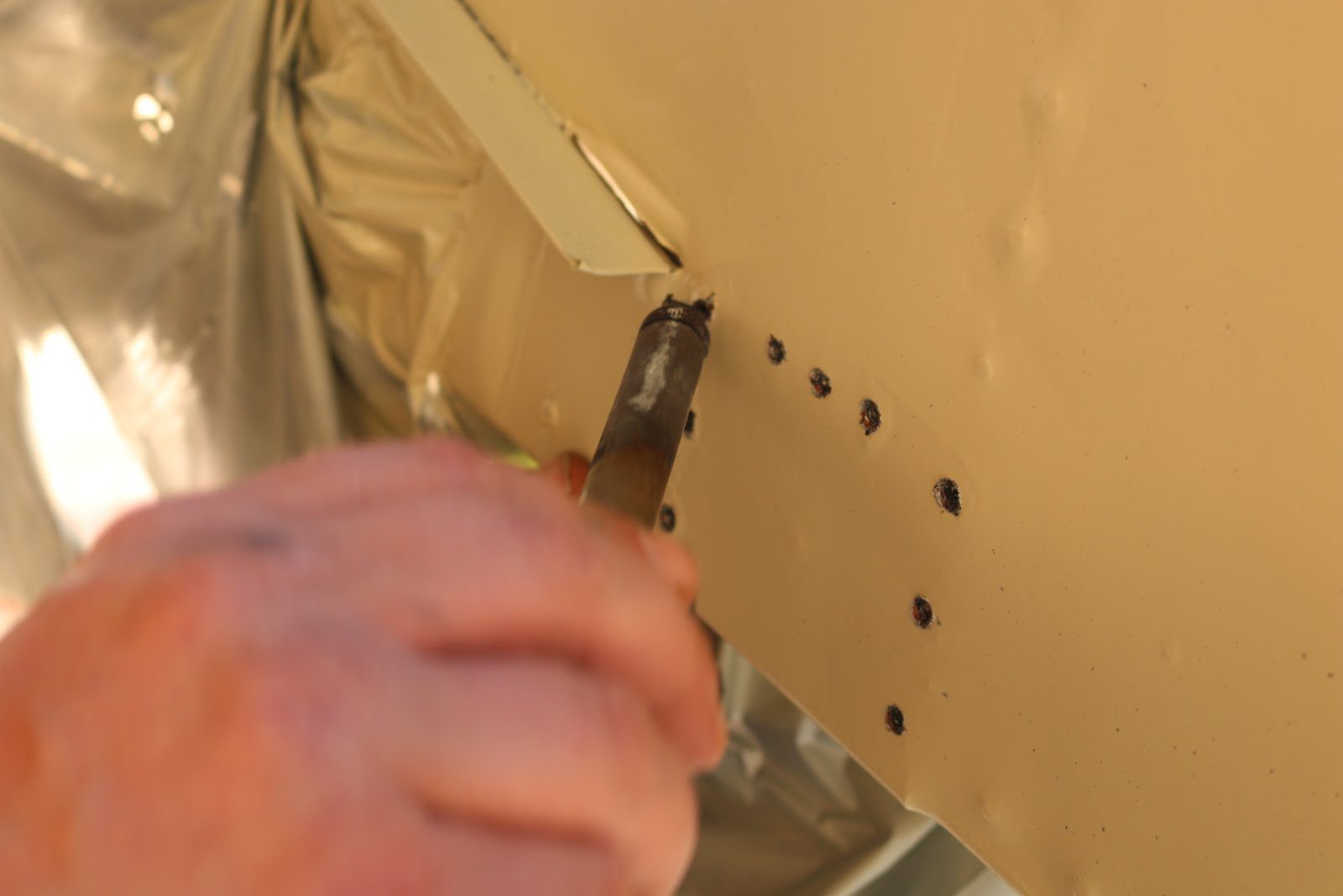
The development of the new rear wing spar attachment fitting was completed after we had the aircraft covered with dope and fabric.
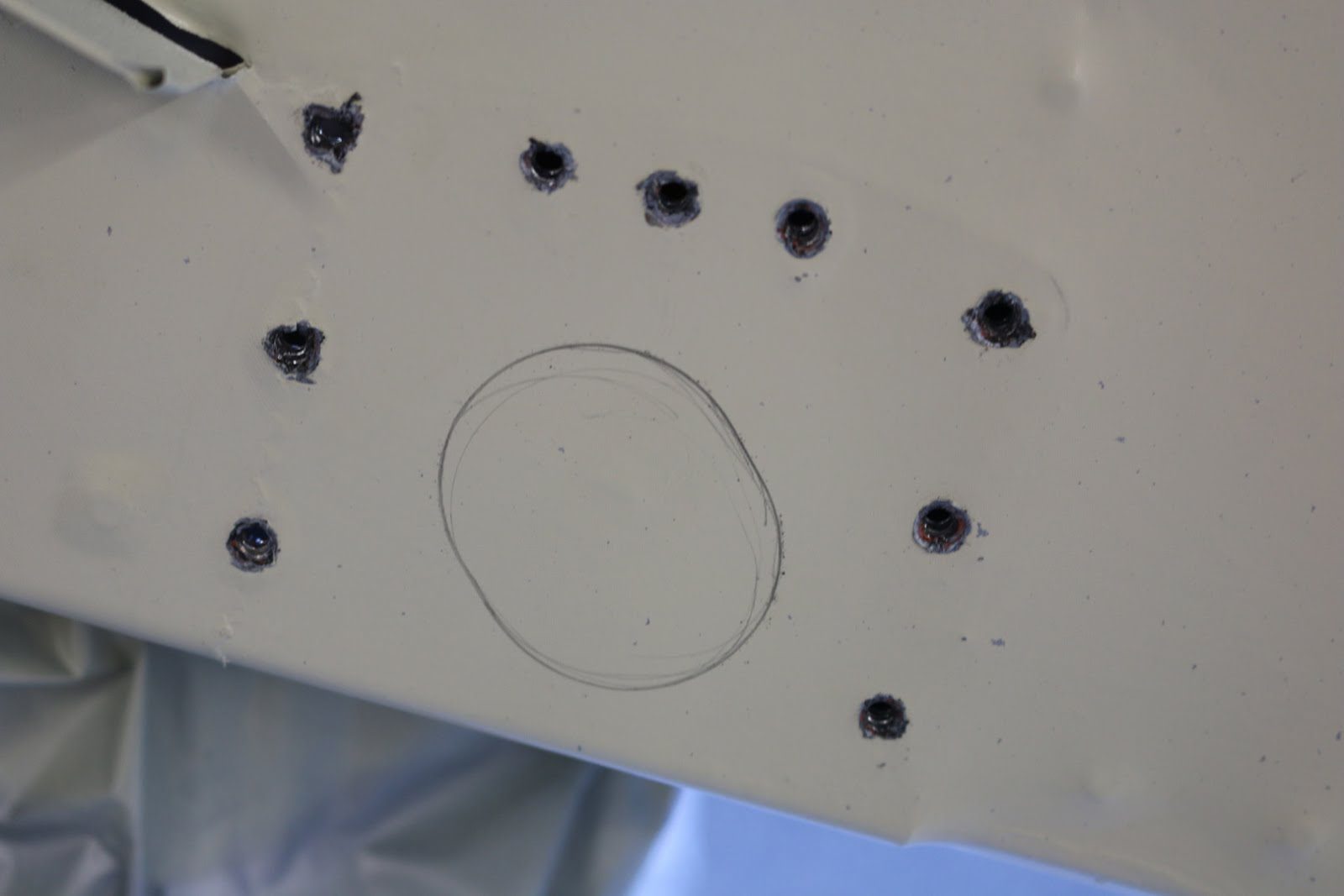
This required that we drill out the existing rivets through the fabric and then take a soldering iron to the fabric to burn off the fabric around the rivet holes.
Once the rivet holes were cleaned up and the modification to the center attachment hole is drilled with a whole saw, we will be able to put the rear spar attachment fitting directly over the existing fabric.
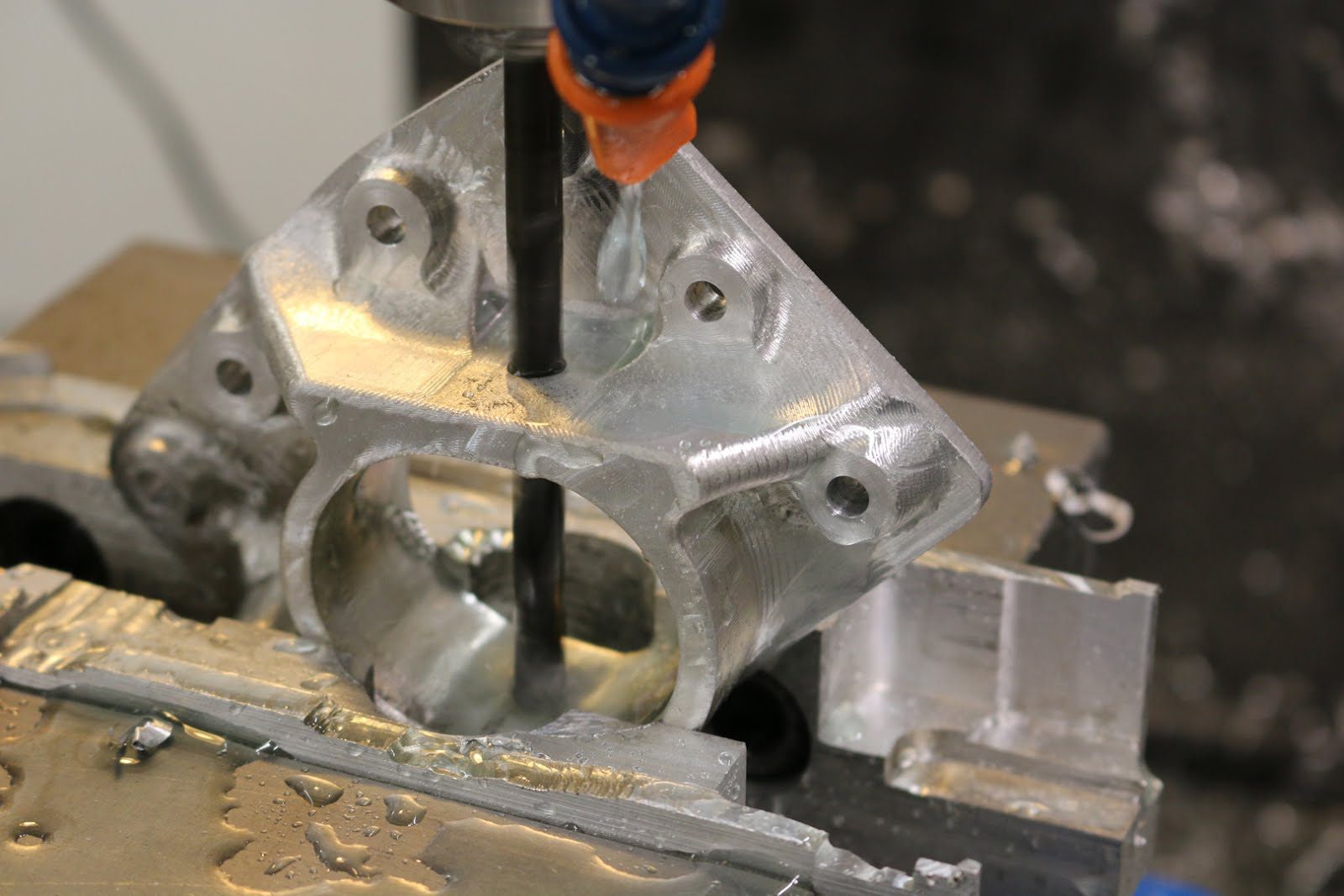
The final machining process is taking place on all of the rear spar attachment fittings.
This involves positioning the fittings and drilling the 1/4 inch attachment hole through the remaining part of the fitting.
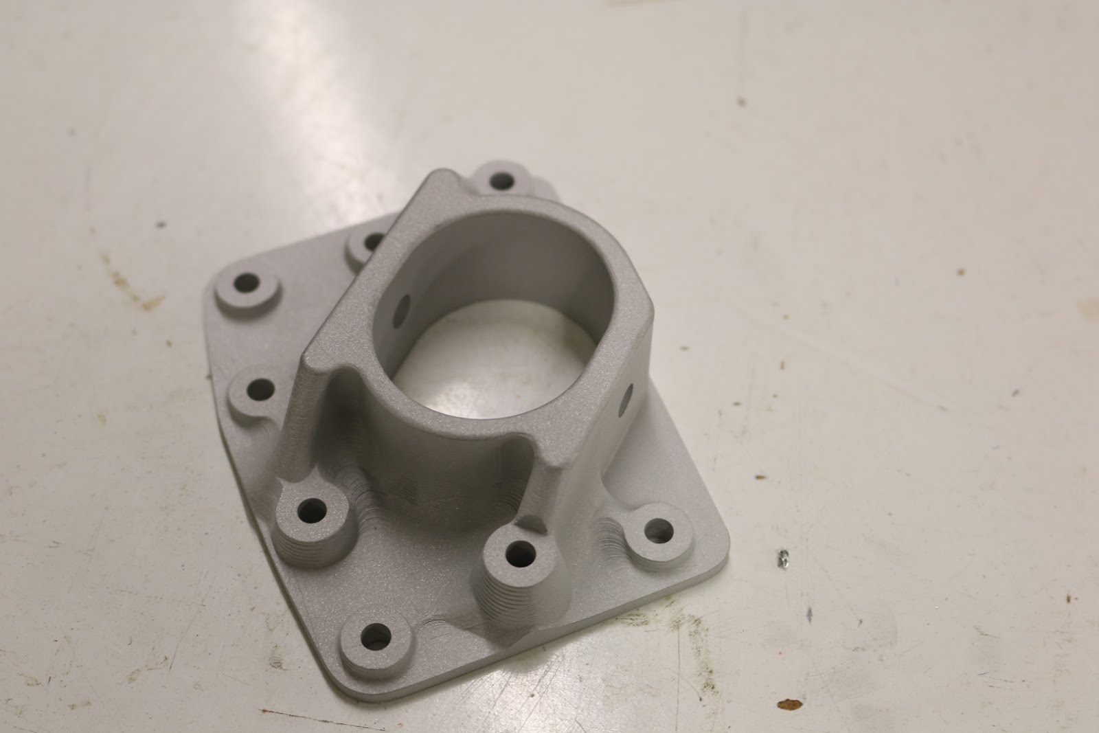
Next the fitting is Deburred and sandblasted.
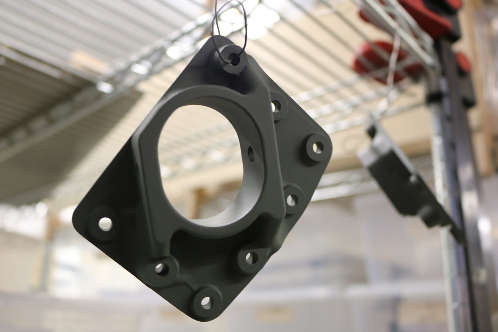
After the part comes out of the sandblaster we will paint it with a coat of etching primer. Since the fuselage frame is being painted this will just provide a base coat for the poly tone to stick to.
February 8, 2016 New Files Added to the Builders Database
The main landing gear truss assembly is a relatively simple design and easy to manufacture.
Even with this simple design we are trying to build the templates for every single part on the aircraft.
These templates have not to date been added to the builders database.
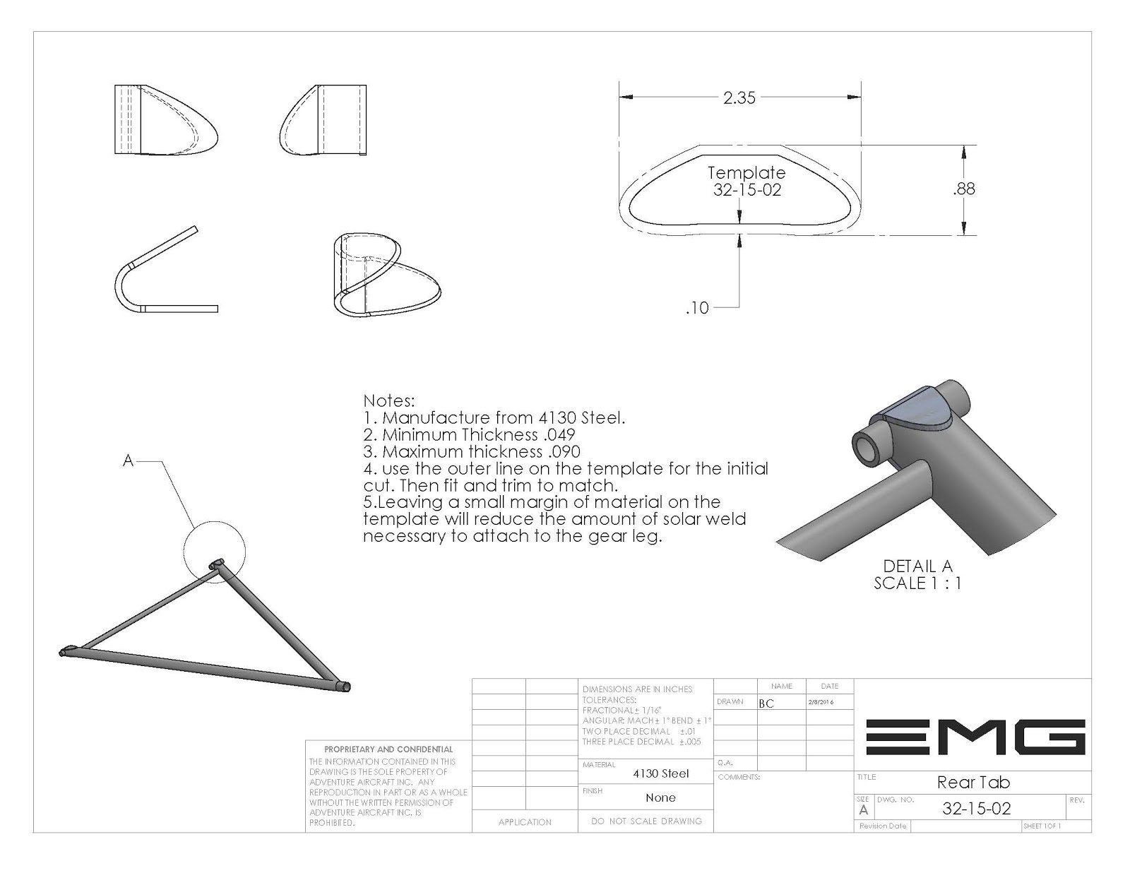
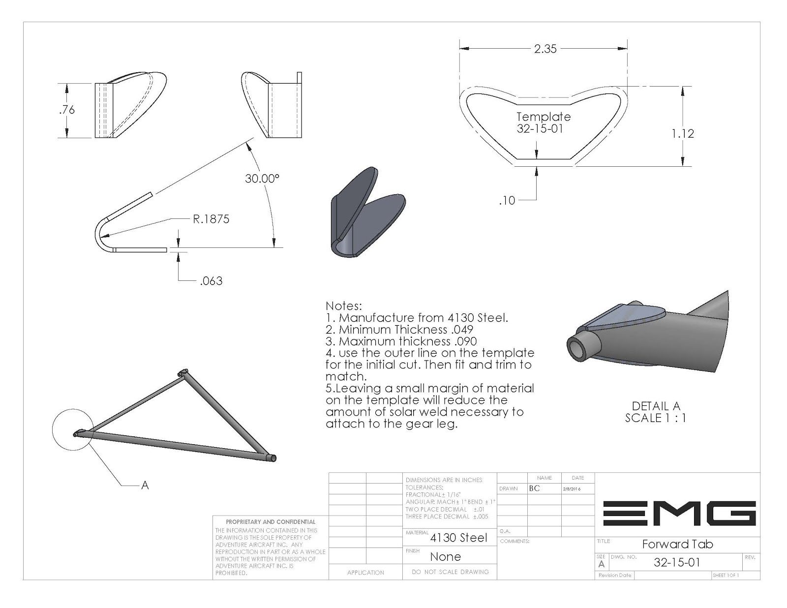
The best way to manufacture these parts is simply to print the PDF file from the database at 100% scale.
Spray a small amount of contact cement onto the back of the page in the area where the template exists.
Stick the template directly onto the 4130 sheet-metal.
Than simply cut the profile using a metal cutting bandsaw.
Link To Forward Tab PDF File Link To Rear Tab PDF File
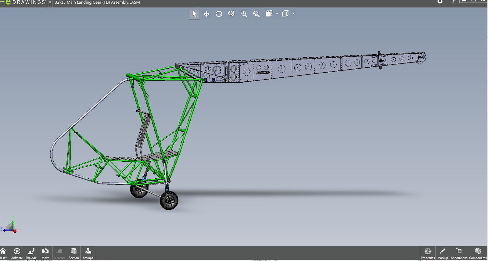
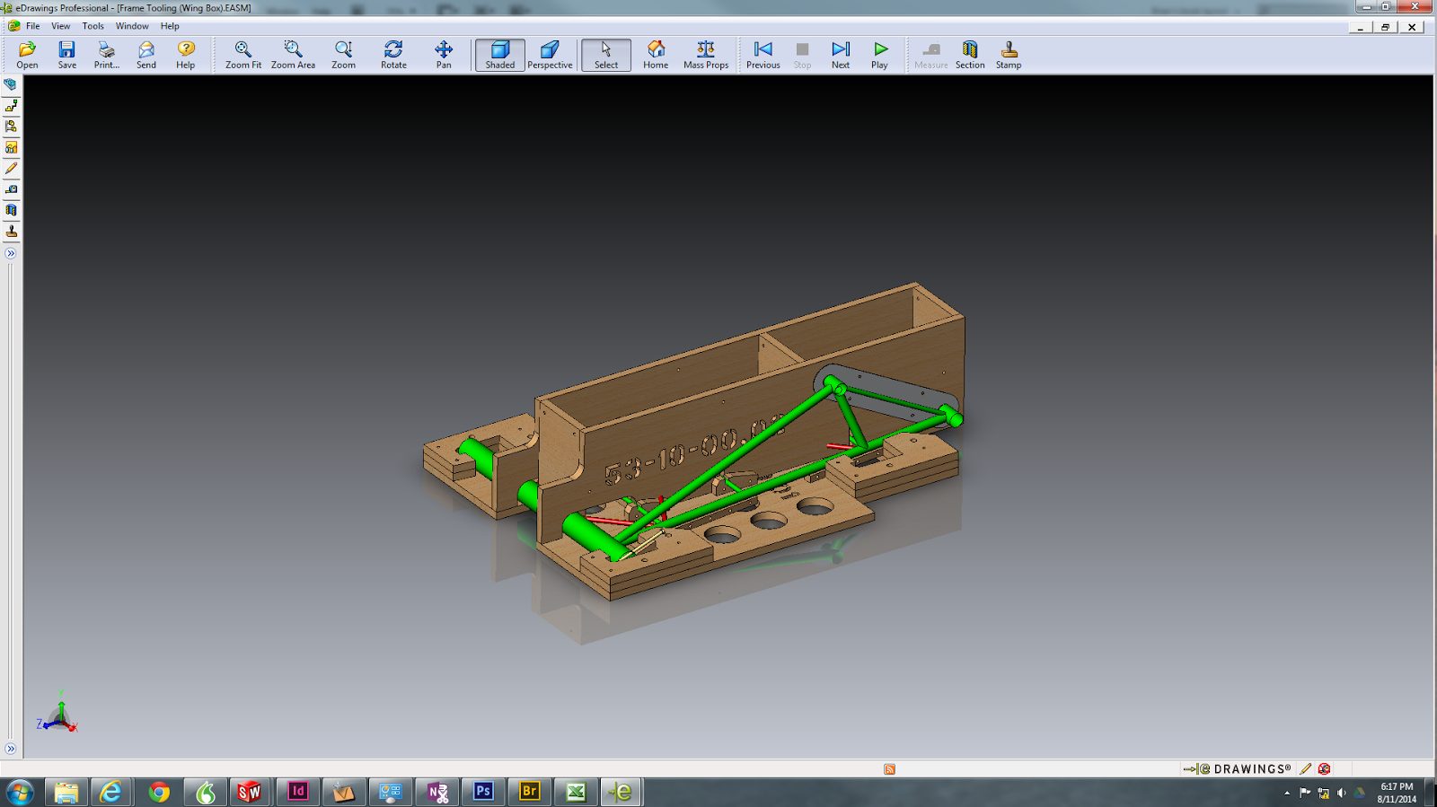
Contained within the builders database are many e-drawings. These can be downloaded and opened with free software from E-drawings. If you do not have a copy of E-drawings you can go to the E-drawings website and download the free E-drawings viewer.
Link To Landing Gear E-Drawing
February 7, 2016
Charlie Becker
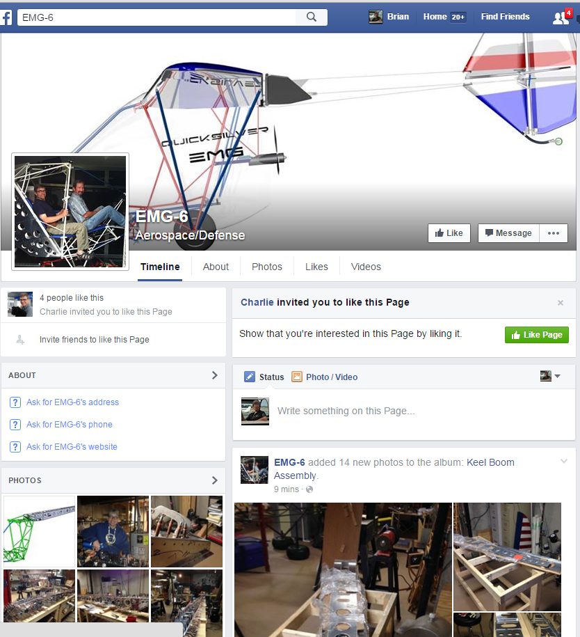
Charlie Becker is director of communities for EAA (Experiment Aircraft Association)
Charlie is one of the builders of the EMG-6 aircraft. Of the 9 customer aircraft being built right now, Charlie is leading the pack. Charlie has also set up a Facebook page and is doing an excellent job of keeping up-to-date with his progress on his aircraft.
Click Here to Link the Charlie’s Facebook Page
February 6, 2016 The EMG-6 Goes Open Source
Breaking News
We have decided to change our basic premise on marketing and selling the EMG-6. Our confidence level in the basic design of the aircraft is so high that we feel we no longer wish to hold it back from the general public. Working as in the model of Google, we feel that in the long run we will be able to monetize a project to recoup our investment. From the very beginning we have elected to not take on investors and simply develop the aircraft at a pace that we could fund in-house. Many of the new builders may not purchase very many parts at all, but many of them will be purchasing parts on a regular basis. We believe we can make a living off of the small margins. In addition many customers will probably want fast build kits which we will be able to supply.
We are allowing the general public to have access to most all of the drawings and plans before they make a commitment to purchase or build an aircraft. Not only that but they will now have as much access as any of the paid builders. And anyone interested in building the aircraft could get started immediately.
Although we’re giving away a tremendous amount of our intellectual property for free, we believe that by making it more financially feasible for the average person to build the aircraft, that we will in the long run make up for any lost revenue by selling fewer parts but to more Builders.
Our method for encouraging builders to register and get a serial number will simply be based on providing support, updates, and the ability to purchase parts tied directly to the serial number that they have. The early serial numbers will also have priority when it comes to getting kits and parts. In addition we plan to offer many additional amenities to the registered builders.
Part of our desire to make this product open source is the overwhelming desire for the aircraft in other countries other than the United States. This will make the process of working with dealers and customers in foreign countries much easier.
Additionally the amount of work necessary to provide web-based updates to customers holding serial numbers and still providing useful information to the general public seems unnecessary and redundant.
We also recognize that there may be others in other countries wishing to steal our design and start producing the aircraft themselves. And we have thought this through and have a strategy in place that will protect our copyrighted design and drawings. In addition it’s extremely difficult to compete with a company that gives away its product for free. We recognize from the very beginning that this project is a labor of love first and a business opportunity second. We are trusting that the community of aircraft builders will look out for our best interests. With today’s world of social media and the Internet, I can’t believe any company would invest the amount of money that we have invested simply to steal our design and share in a fairy small market only to undergo the shame and ridicule that would Inevitably follow. I’ve seen other aviation companies go belly up with far smaller indiscretions.
We will be holding out some proprietary information from the builders database that we will be sharing with our dealer network around the world in order for them to be able to produce parts locally. In addition we continue to upgrade the drawings on a regular basis.
We believe that this policy change will be for the better and is the right choice, however if everything goes sideways at looks like it was a bad choice we can always change back.
You can help our cause by simply spreading the word about the EMG-6 aircraft.
Post your comments of encouragement or if you think I’m off base you can let me know that as well.
Link To The Builders Data Base
February 5, 2016 More updates to the Builder Files
Continued renovation to the website structure and accessibility to the existing builder files.We are just starting with the foundation for the structure to be able to start adding the existing files. So there isn’t much data available yet. But the existing files that we do have you can kind of see the basis for what were eventually going to have. Click here to see the outline.
New batteries for electric powered aircraft from Donald Linback (Click Here)
February 4, 2016 Builder Files new additions to the Website
As part of the new website renovation we are working on adding all of the builder files to the website. One of our core missions is always been to make this aircraft one of the most innovative building projects around. With the primary focus associated with allowing the builders to build as much of the aircraft is there comfortable with. Providing as much builder support in the form of builder videos, PDF files, E drawings, and now Web-based building instructions. in the long run we feel that this will provide a more comprehensive method of making changes to the builders database and providing instantaneous feedback and updates to the existing builders. This will take a significant amount of time and effort to get the information to the website and updated but as it stands right now we are still ahead of all of the builders that are currently building their aircraft. Click on this link to view the most recent addition
February 4, 2016 Website Maintenance Continues.
As you may have noticed there’s major repair work going to the website and blog. You’ll see quite a few changes in the next couple of days. Hang tight were continuing to blog at the same time while we make changes to the website. All of the blogging data still remains but some of it may be difficult to get at for the next couple of days.
February 2, 2016 Flight Planning for May
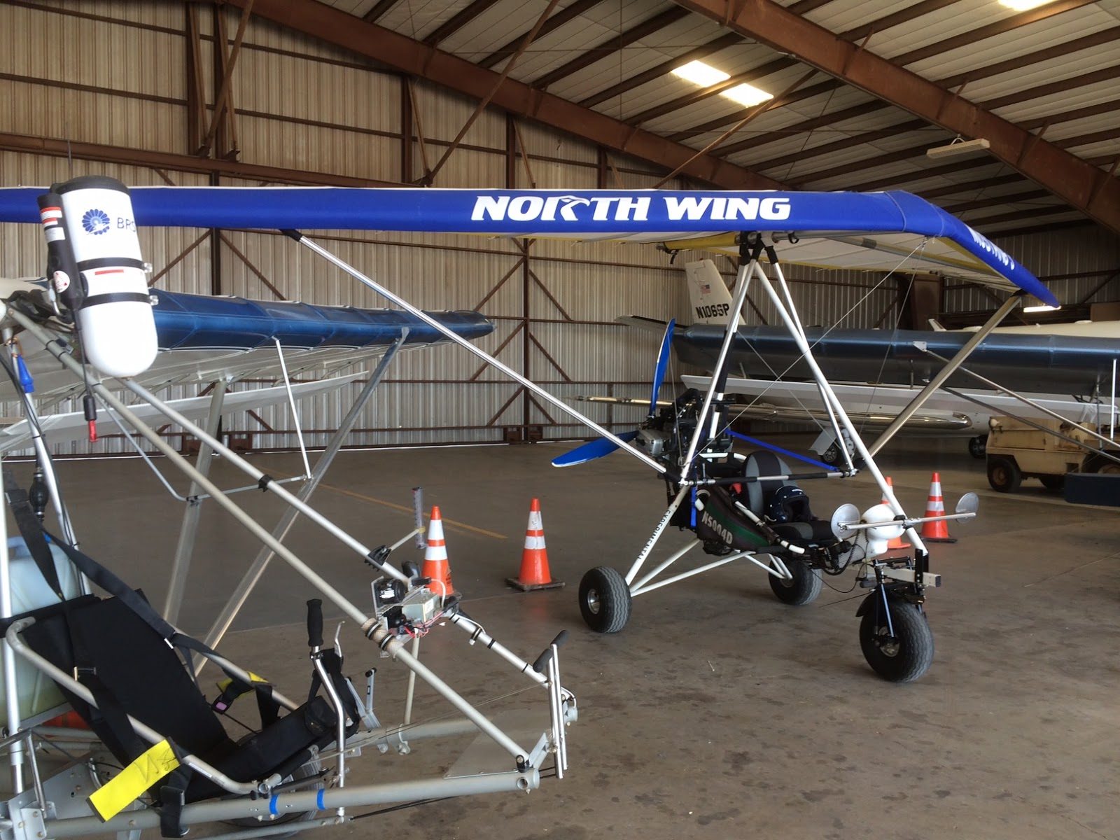
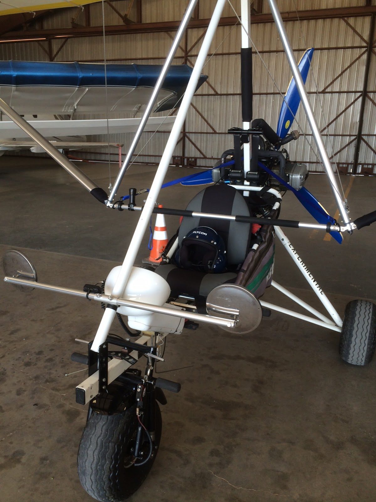
This picture was taken where he tugged at the US Nationals HG competition at Big Spring, TX.
Gregg has indicated that he’s up for a few monster tows. (High-Altitude)
With Gregg’s commitment to this date we will be working very hard to have at least one of the EMG-6’s ready for the toll operations. With Gregg’s 110 hp lightweight aircraft we should have performance towing that easily doubles the amount of performance that we were able to get out of the 65 hp GT-500 that we have currently been towing with.
February 1, 2016 Rear Spar Attach Fitting
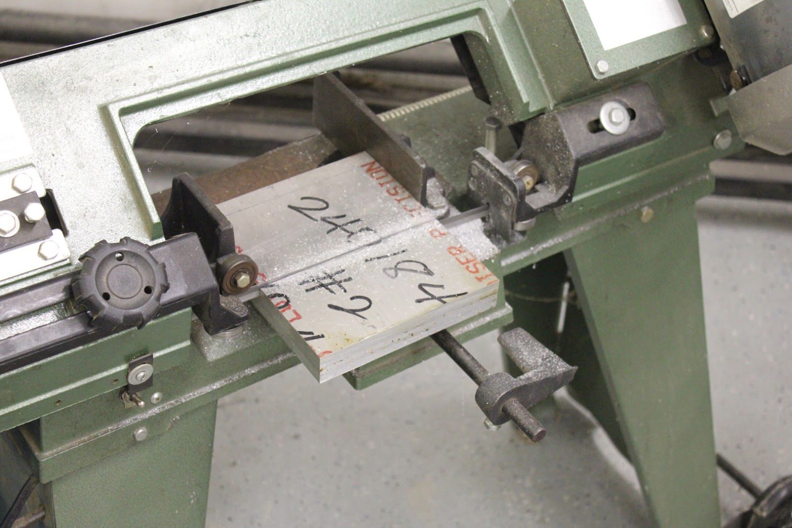
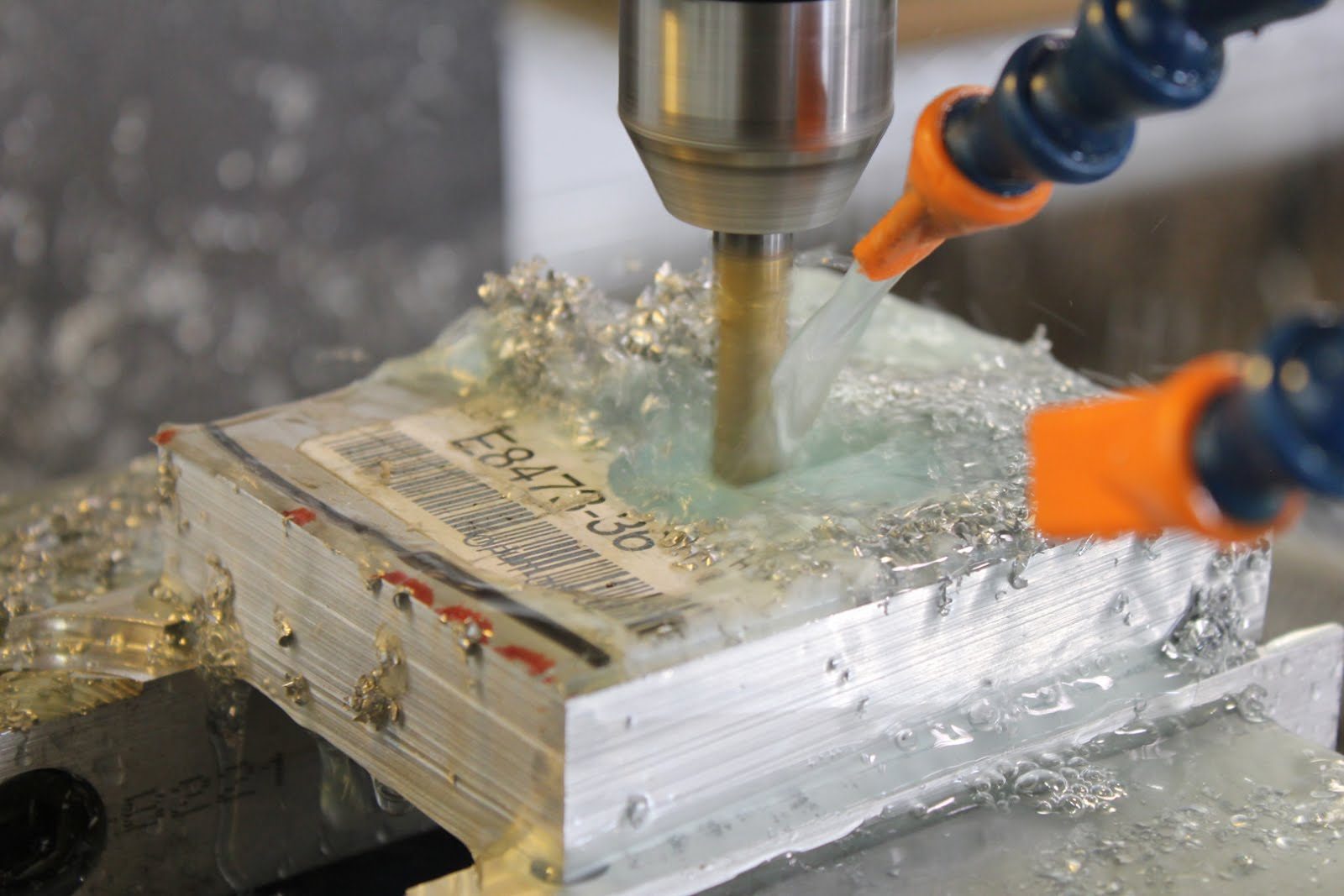
For the last couple of days we’ve been working on manufacturing up the last of the rear spar wing attach fittings that retrofits onto the EMG-6 L/D Aircraft prototype.
The fittings are machined from 1 inch thick 6061 T6 aluminum.
We use a metal cutting band-saw to cut the parts into blanks to be put into the milling machine.
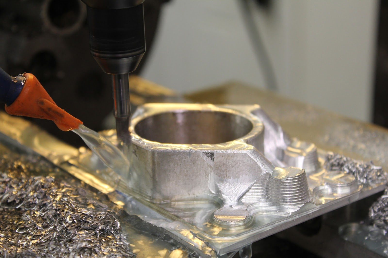
In this picture here you can see the beginning of the finish cut.
And the last step is drilling the attachment holes that will bolt to the fuselage boom assembly.
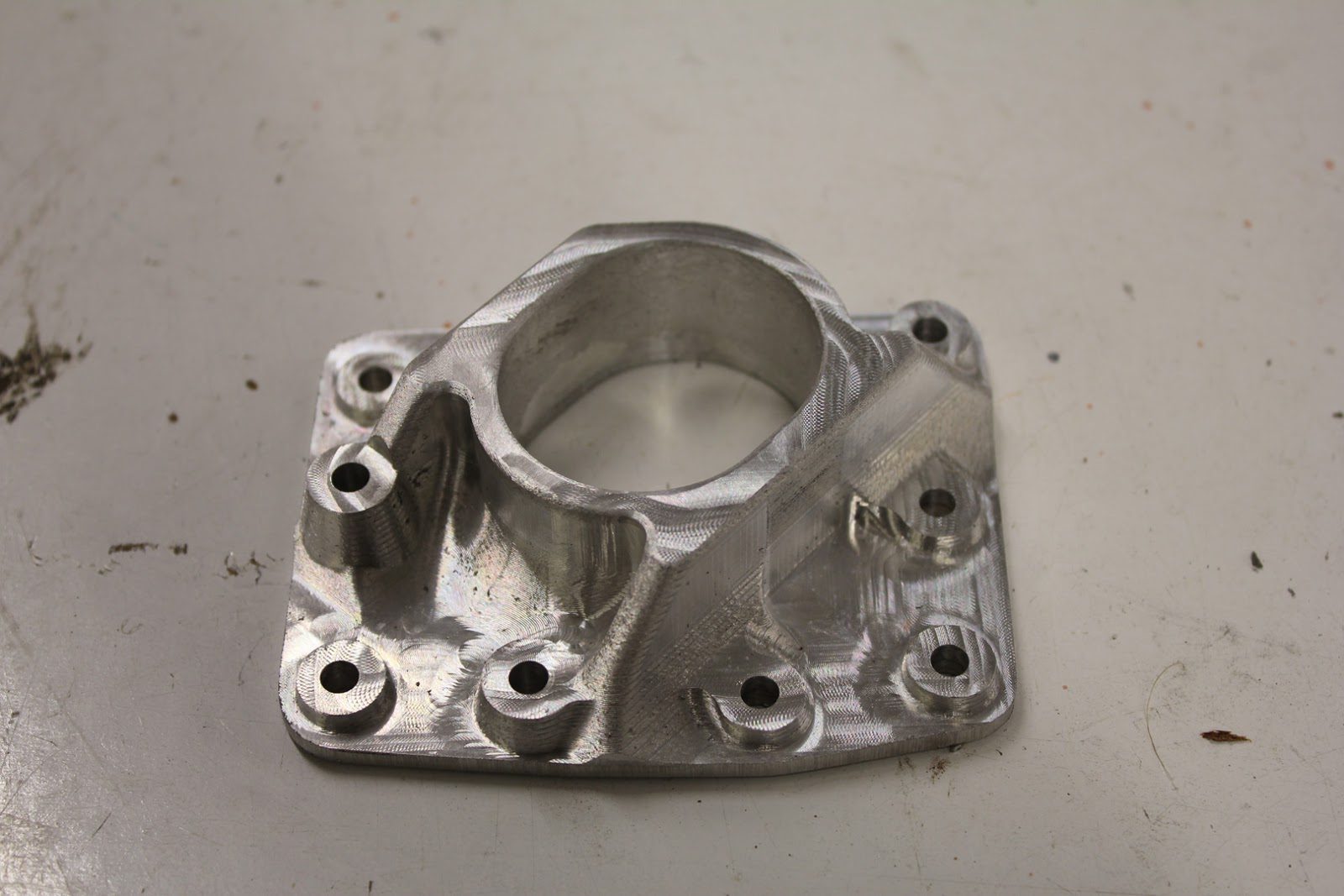
The last step remaining is to drill the wing spar attach holes horizontally.
This will take place once This series of components is finished being cut.
At that point we will cut and indexing holder into the milling vise to hold the fittings for the attached hole drilling process.
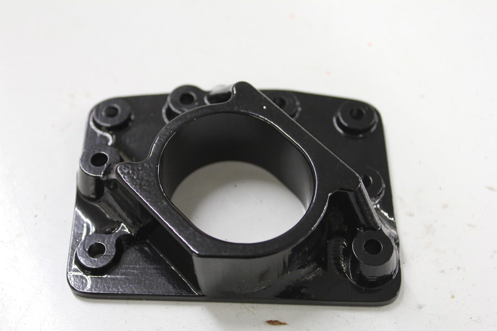
One of the fittings after bead blasting and powder coating.
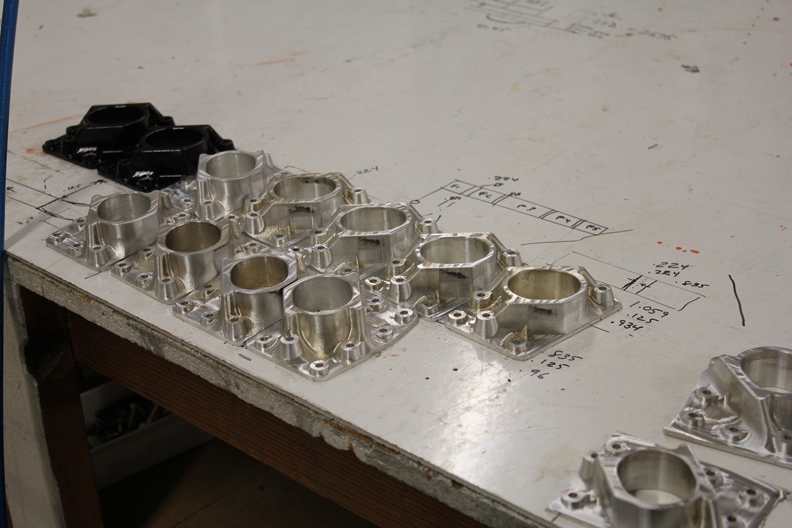
Like with many of these parts it reduces the cost substantially if we can make many all at one point in time.
Most of the cost is the setup and material cost.
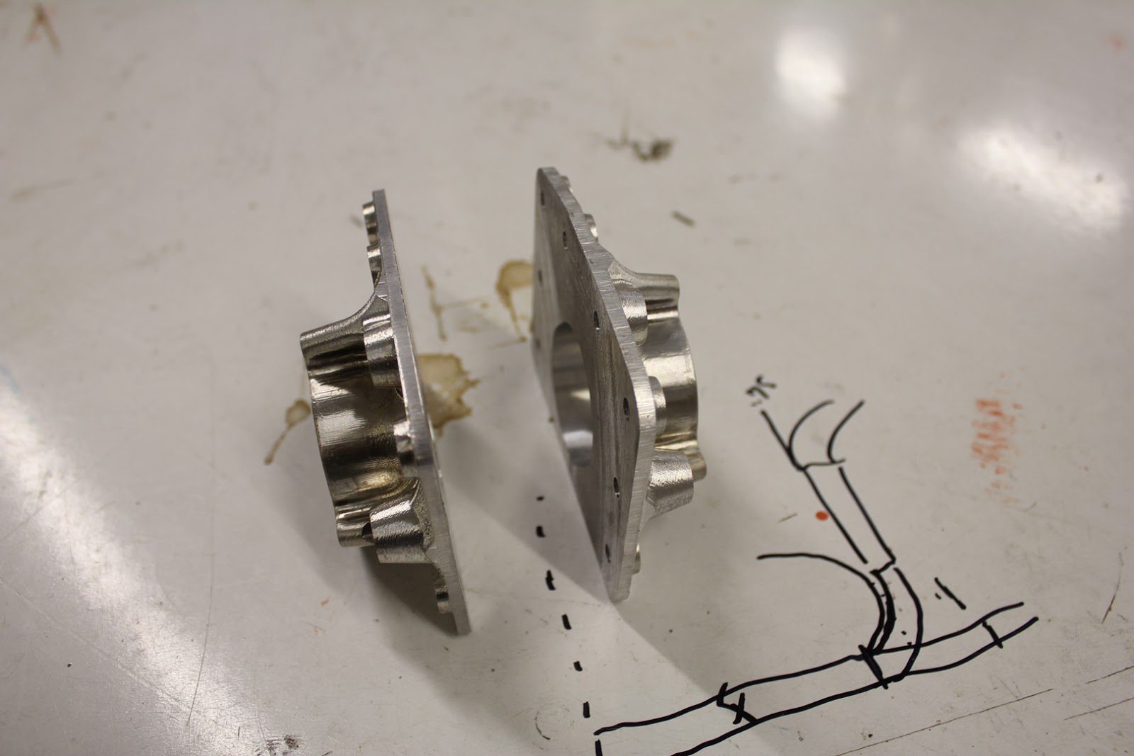
The rear spar attach fittings require both a left and a right fitting.
These can be cut in the same holding fixture but are completely different tool paths for each side.
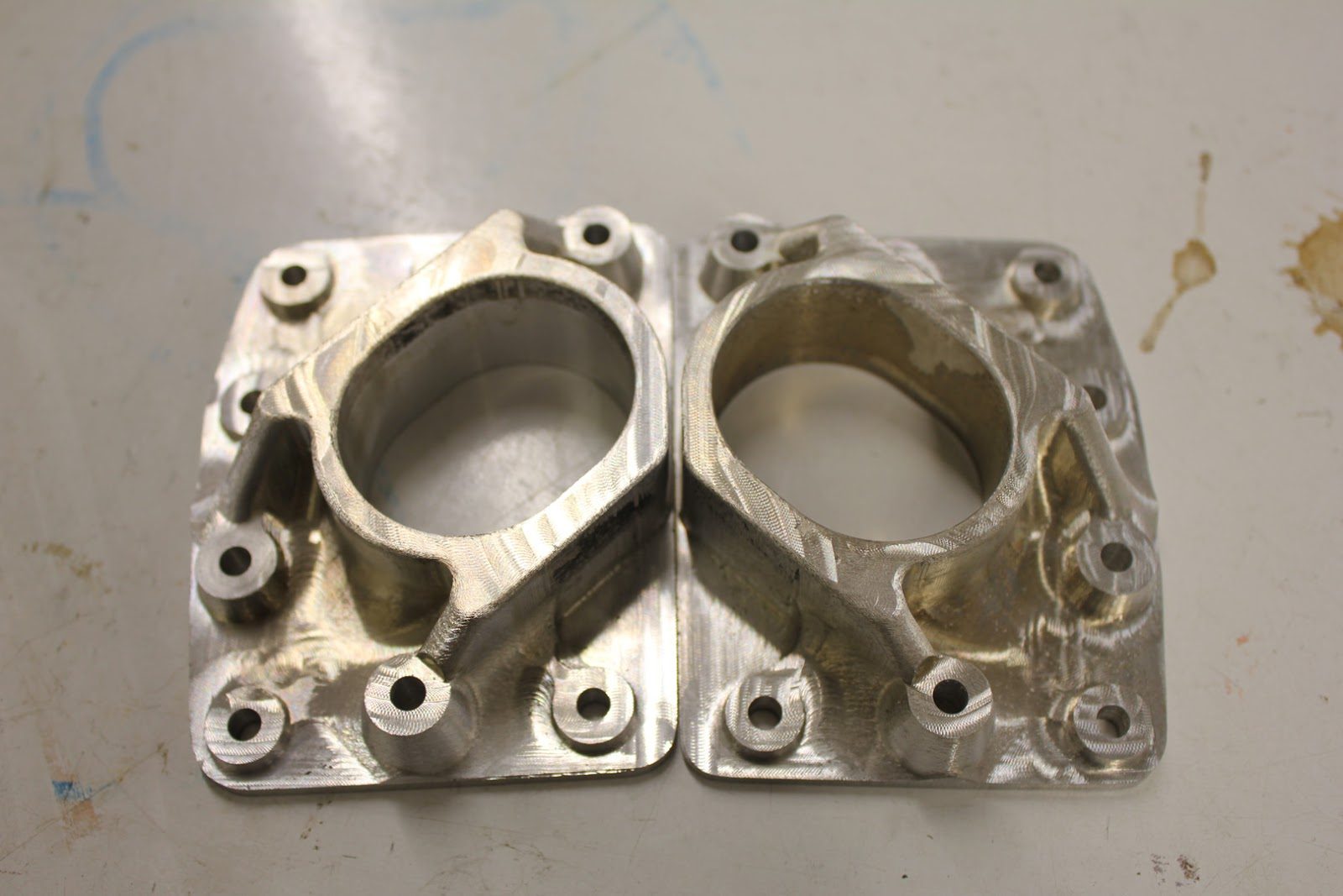
Another view of the right and left rear spar wing attach fittings.