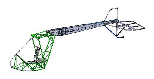
Builders Guide
55 Stabilizers
Horizontal Stabilizer Main Spar Sub-assembly
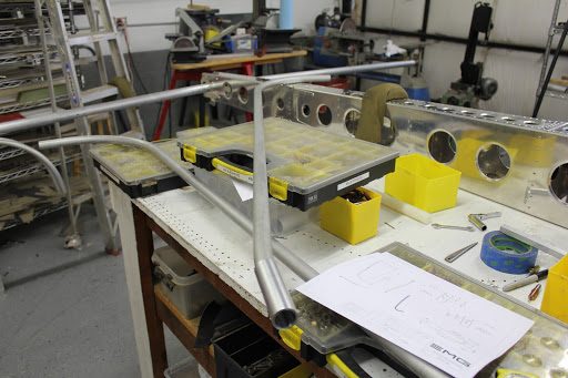
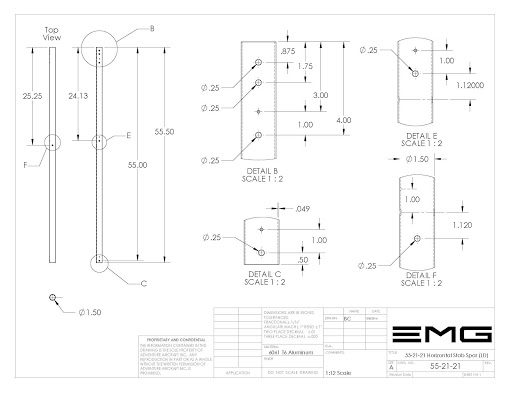
We will start the construction of the horizontal stabilizer assembly by beginning with the main spar sub-assemblies. This consists of the main spar to with reinforcing sleeves inserted in 3 locations.
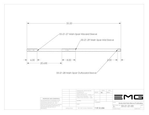
We will we measuring and marking the spar tube using the ordinate system. The inboard section of the tube is the origin and all marks will be made with a tape measure measuring from the inboard edge outboard.
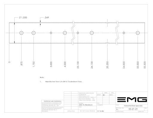
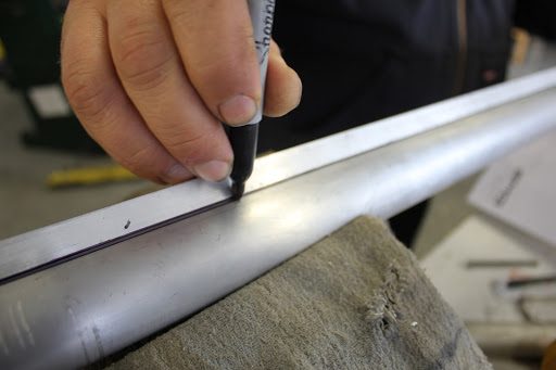
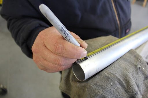
Using a fine point magic marker to ensure that the distances for the holes are accurate. Layout each one of the holes along the length of the horizontal stabilizer spar and mark and label if necessary.
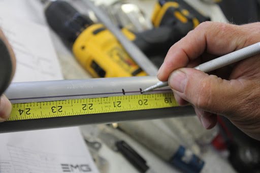
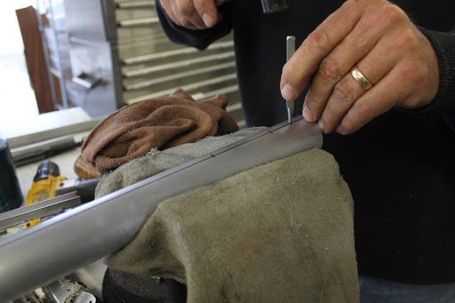
We have found a very effective way of marking the spar accurately. If we use a larger magic marker to create a black area. Then we can come back with a scribe and make a very precise line. Keep in mind that the scribe line needs to be within the circumference of the hole that your drilling. Even a very small tick mark will allow you to use a center punch to accurately position for the drilling process.
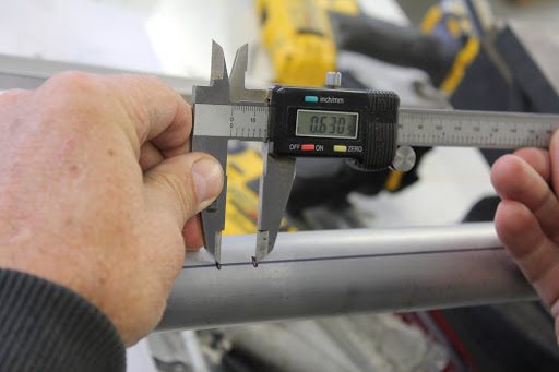
To increase the accuracy even greater, you can use a tape measure to mark a reference line at the nearest inch. And then use a pair of calipers to carry the additional dimension to the .001 level of accuracy.
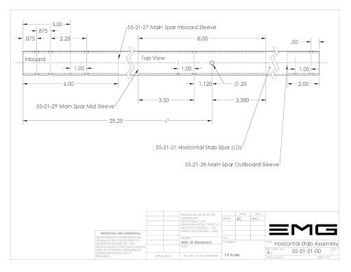
The only hole that penetrates the spar through the top of the horizontal stabilizer spar is the hole that locates the lift strut attach eye bolt. All of the other holes are located on the forward plane of the horizontal stabilizer spar.
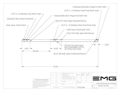
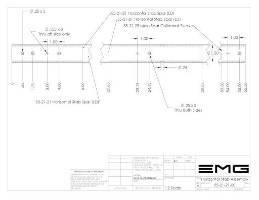
Once we have completed the layout and marking of all of the holes to be drilled on the forward side of the horizontal stabilizer spar we can center punch each one of these.
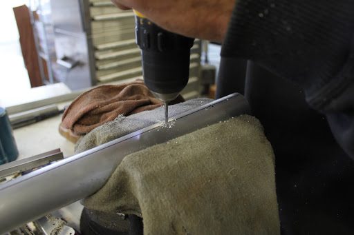
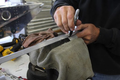
In our procedures we like to drill all of the holes with a 1/8 inch or #30 drill bit. This way we have a pilot hole for the holes that will be converted to 3/16 and eventually 1/4 and the holes for the pop rivets that hold the sleeves in position will be pre-drilled for the sleeve positioning. The next step will be to prepare each one of the internal sleeves. We will need to mark them and drill the hole for the .125 inch pop rivet hole. And just like the main spar we will center punch.
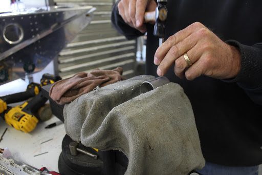
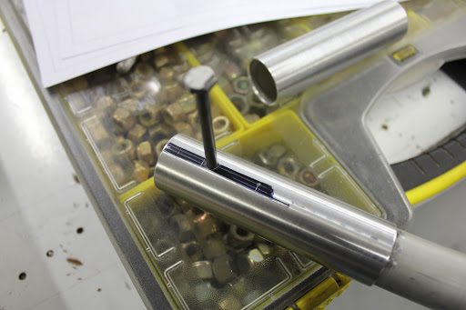
Next we will drill the 1/8 inch rivet holes into each one of the internal sleeves. In this picture here we are starting with the outboard sleeve as an example.
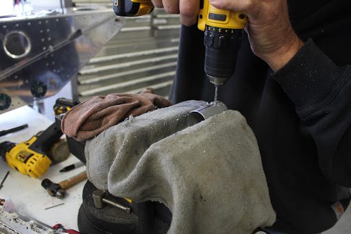
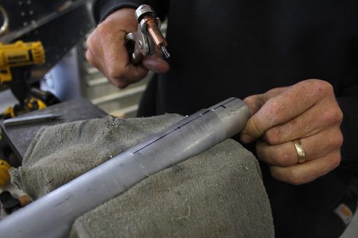
Next we will insert the sleeve into the main spar and align the rivet holes. Then we can insert a 1/8 inch copper Cleco to hold the sleeve in place on the horizontal stabilizer spar. Now remove the Cleco and installed the CCP 4-2 stainless steel pop rivet to hold the inner sleeve in place before you drill.
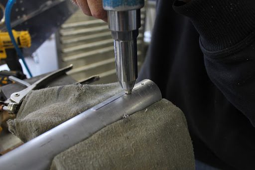
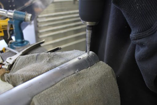
Next we can drill the hole through the inner sleeve using the spar tube as a guide. We use a #2 uni-bit. Keep in mind we are only drilling through one side of the spar at this time. And we use the Uni bit only for the purpose of drilling through a single side of the spar. The #2 in a bit is the only one that has a long enough shank on each size to be able to do this with. Once we have a 3/16 inch hole through both the spar tube and the outboard sleeve we can take the assembly over to the drill press with the V block set up and drill completely through the spar ensuring that the whole is centered for the adjacent side.
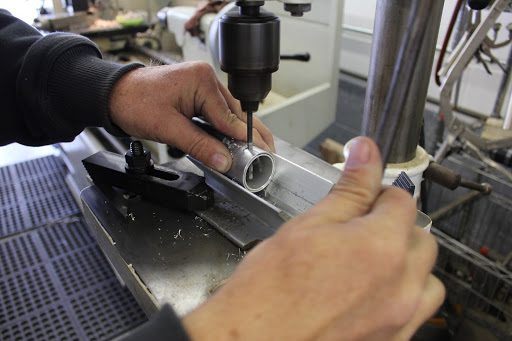
We can now take are #2 Uni bit and using the sleeve as a guide we can drill through the spar to increase the outboard elevator hinge bolt hole to a 1/4 inch diameter size. Using the unit bit works very well because it maintains very good consentricity when drilling through thin-walled tubing.
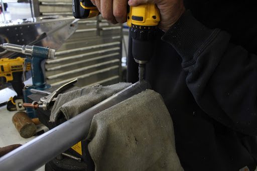
We can now rotate the tube 180° and drill the 3/16 hole that we previously drilled all the way through the spar on the drill press to a 1/4 inch diameter hole using the #2 Uni bit.
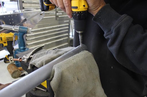
We can now temporarily insert a 1/4 inch diameter AN 4 bolt. Using this drilling method will normally result in a very clean hole for the through bolt. It should not have any resistance to turning but it should also not be loose or wobbly in the bolt holes.
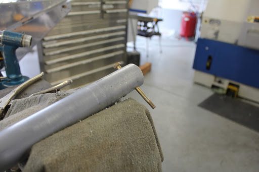
Next because it’s in the middle we will insert the Main Spar Mid-Sleeve part number 55-21-29. Note that the hole location for the CCP 4-2 is located on the inboard side of the sleeve inboard from the mid-tube attach bolthole.
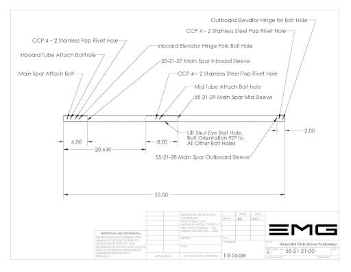
The main spar mid-sleeve is manufactured from 1.375×.058 6061 T6 aluminum tube. Because of the way that we are externally referencing all of the bolt holes for the drilling process only hole that needs to be drilled in this tube is the 1/8 inch stainless steel pop rivet hole is located 2.5 inches from the end of the inboard side of the midspan sleeve.
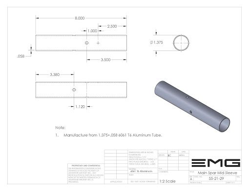
Once you have drilled the 1/8 inch or #30 hole 2.5 inches from the end of the tube and slide it into place while lining it up up with the 1/8 inch hole that is located 23.130 inches from the inboard edge of the horizontal stabilizer spar.
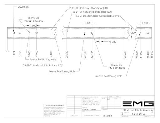
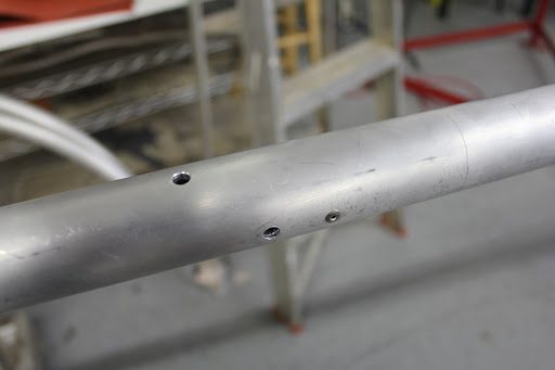
In this picture here we have the mid-sleeve installed. The CCP4 – 2 stainless steel pop rivet Installed holding the sleeve in position. The mid-tube attach bolthole and the lift strut eye bolt attach hole have both been drilled using the procedures that we talked about before. Initial holes drilled to 3/16 inch, drill press to drill through the entire spar at 3/16 inch, and then each hole upsized with a # 2 Uni bit to a 1/4 inch hole size. Running the unit bit up to the next hole size and just kissing the aluminum will act as a deburring tool. Don’t overly deburr.
The next and last sleeve that we have to install is the main spar inboard sleeve. This is part number 55-21-27. This 6 inch long sleeve is located at the inboard attach location for the horizontal stabilizer.
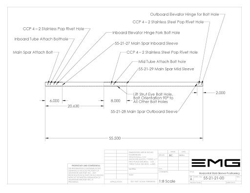
Once again the only hole that is necessary to drill in the main spar inboard sleeve is the 1/8 inch diameter hole that is located at the 3 inch dimension.
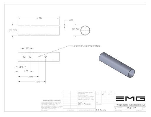
In addition we are going to need the horizontal stabilizer aft socket part number 55-21-42.
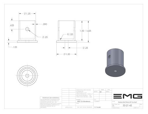
55-21-42 Horizontal Stabilizer Aft Socket
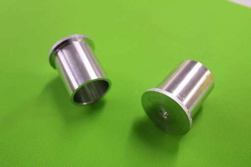
The aft socket will fit tightly inside of the inboard sleeve.
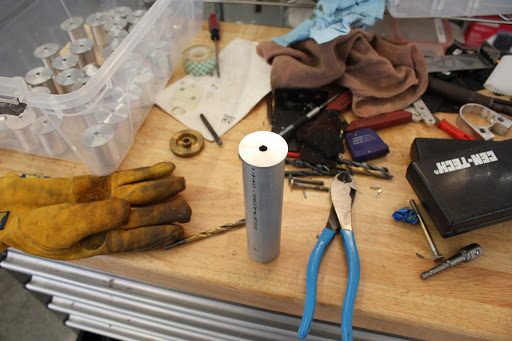
The sleeve and socket will then be pushed in flush against the end of the main spar tube.
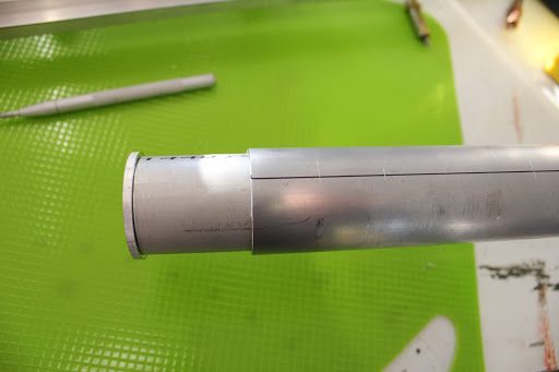
The inboard sleeve will be positioned just as we did the previous 2 sleeves. We will align the 1/8 inch rivet holes and install a 1/8 inch CCP 4 – 2 stainless steel pop rivet. The other holes will be predrilled with a 3/16 inch hole, drilled through on the drill press and V block, and then upsize to 1/4 inch.
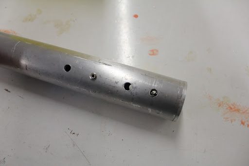
The only difference on the sleeve is that you have to remember that the Aft main Horizontal stabilizers are socket will be able to rotate freely and as such you will have to use a bolt to temporarily position it while drilling the adjacent side.
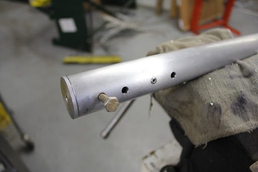
Once the aft socket has been drilled through with the main spar it will be able to be removed. This is the method by which the horizontal stabilizer can be removed from the aircraft for transport or storage.
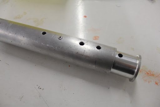
Installation of horizontal stabilizer main spar
We can now start the assembly of the horizontal stabilizer by mounting the Horizontal stabilizer spar socket onto the side of the fuselage boom. This socket will be installed with a AN4 bolt and a nylon nut. The exception to this will be if you are installing the horizontal stabilizer trim system this not and bolt combination will need to utilize a castle nut and cotter key. Either way the Bolt that holds the socket in place should be tensioned enough that it moves with considerable resistance but you can still rotate with your hand by grabbing onto the socket and rotating.
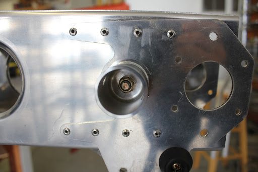
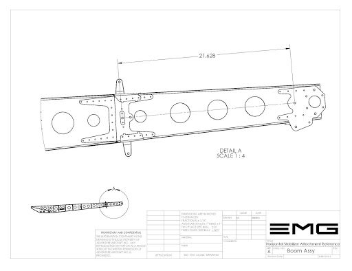
If you are building the horizontal stabilizer with out having previously built the fuselage boom. No problem. Simply find yourself a piece of three-quarter inch plywood or equivalent and placed 2 holes located 21.628 inches from each other to simulate the fuselage boom.
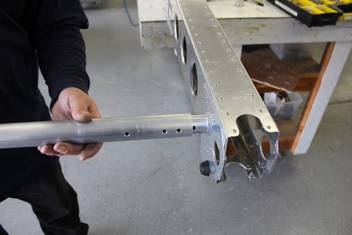
We can now insert the horizontal stabilizer spar on to the horizontal stabilizer spar socket that is previously attached to the fuselage boom.
The positioning of the CCP 4 – 2 stainless steel pop rivets should be on the inside of the horizontal stabilizer or facing forward.
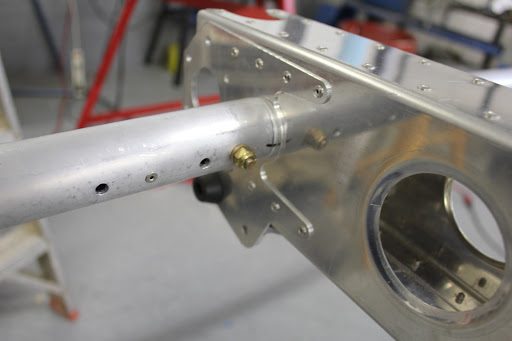
The sides of the fuselage boom can easily support the weight of the horizontal stabilizer however keep in mind that the real strength comes when the list struts are attached to the vertical stabilizer spar. At this point you could overstress the rear section of the fuselage boom assembly by placing too much force onto the spars. Where simply using the fuselage boom as an alignment jig to ensure that we have the proper alignment during the assembly process.
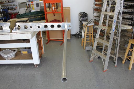
A top view of the horizontal stabilizer spar attach to the socket, attached to the fuselage boom.
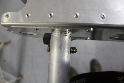
Installation of horizontal stabilizer leading edge tube assembly
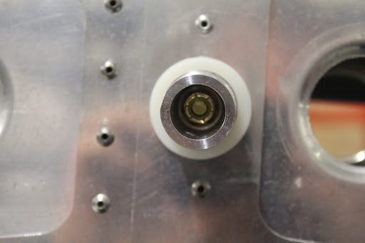
Next we will need to install the horizontal stabilizer forward socket part number 55-21-41. The hardware orientation is shown in the following drawing.
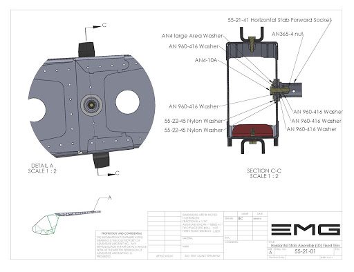
The horizontal stabilizer forward socket is the interface between the horizontal stabilizer leading edge and the side of the fuselage boom.
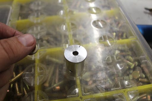
We will be using to AN 960– 416 washers as spacers from the side of the fuselage. This is necessary to accommodate the geometry when switching back and forth from the electric trim system to the fixed stabilizer trim system.
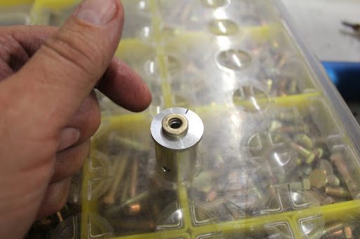
Next we will install the nylon washer Around the perimeter of the 1/4 inch washers .
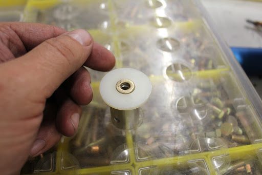
We will insert and AN4-10A bolt with a 1/4 inch larger area washer, to smaller 1/4 inch washers, And another nylon washer on the inside of the fuselage boom.
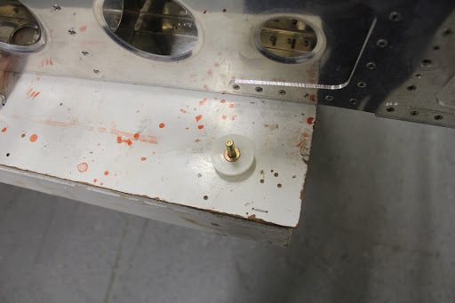
Then follow up with the previously assembled socket, washers, nylon washer assembly that we put together in the previous pictures.
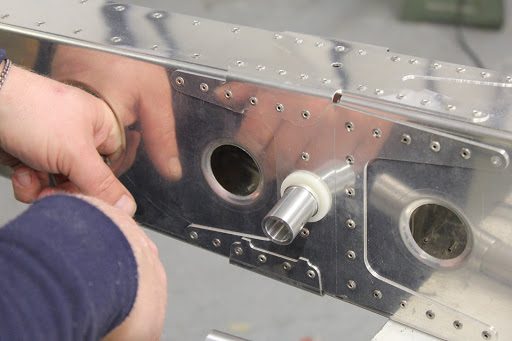
The assembly should be then snuged up to the point that the socket will rotate by hand but should have significant resistance.