Builders Guide
27 Flight Controls
$$$ For Pricing And Purchase Information Visit Our Store (Click Hear)
Builders Database Link to27-41 Rudder Assembly (LD)
PD Rudder Assembly Manual
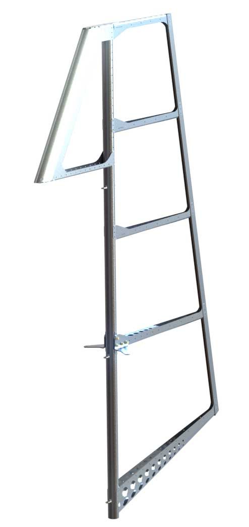
Rudder Assembly 3-D E drawing
PDF 27-41-00-01 Rudder Spar Locations
PDF 27-41-00-05 Rudder Assembly (LD) Overview
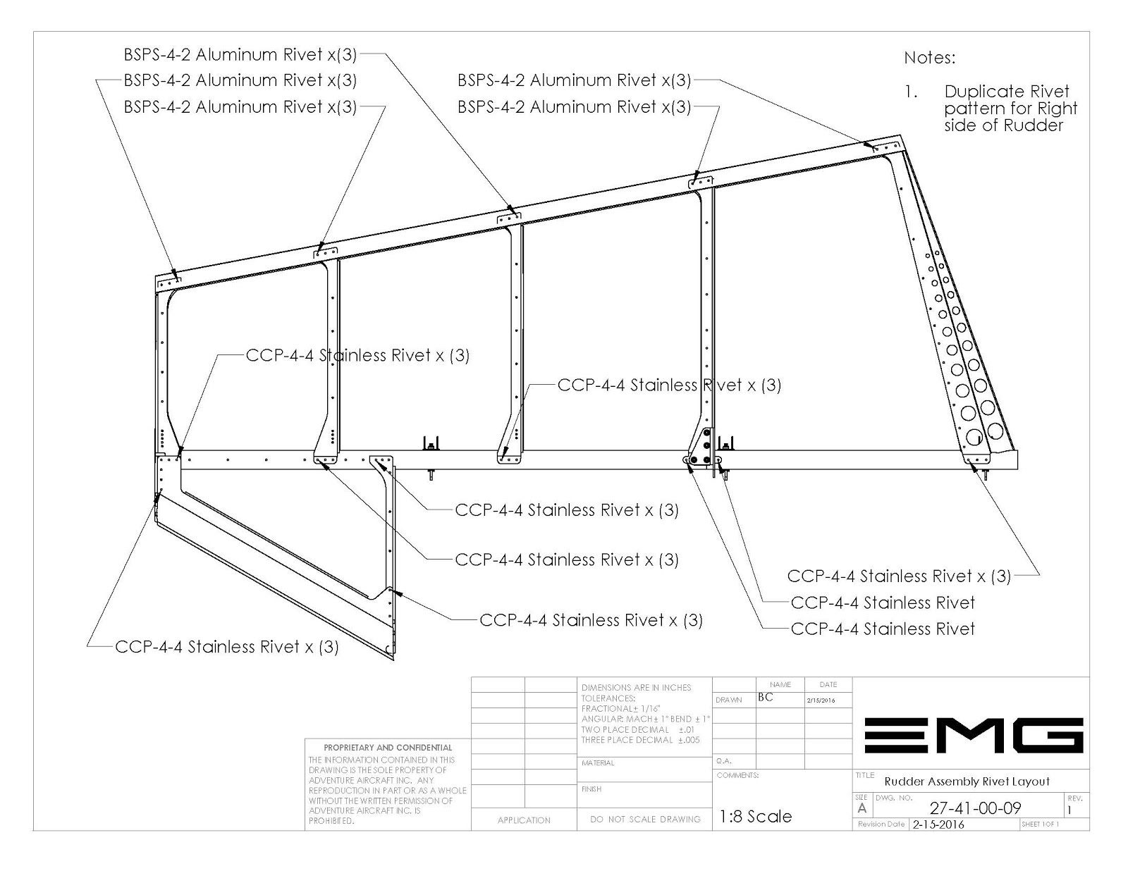
PDF 27-41-00-09 Rudder Assembly (LD) Rivet Layout
PDF 27-41-00-11 Rivet Layout rib number 1 & 2
List of Revisions
Revision 1 (Leading edge Modification)
The original design consisted of a sheet-metal leading-edge. By modifying the leading edge to a smaller wrapped “D” tube construction we were able to reduce the cost of manufacturing of this part. The aesthetic contribution was significantly improved by increasing the radius of the leading edge. And the overall weight of this part was reduced by half. But more importantly it reduced the cost of shipping the entire rudder kit substantially by reducing the shipping box by half of its size.This modification was done without any changes to the original parts configuration and is readily adaptable from one designed to the other.
Video Links
Time Lapse Covering the Rudder Assembly
Rudder Assembly Video
Building the Rudder Spar Video
Rudder assembly Procedures
27-41-00 Rudder Assembly
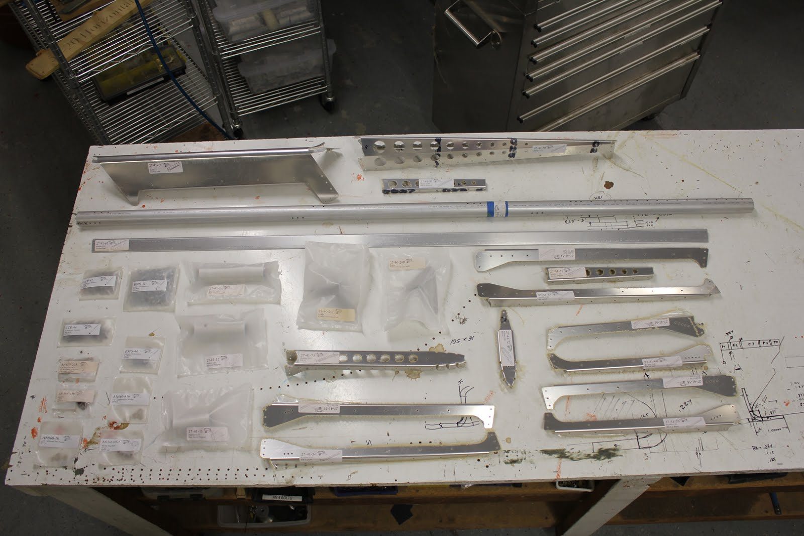
27-41-00 Rudder Assembly Parts List
Rudder Hardware Kit
P/N Nomenclature Quantity
MS21078-4 Nylock Nutplate 3 BSPQ 4-4 .125 x.5 pop rivet aluminum 8* BSPQ 4-2 .125 x.25 pop rivet aluminum 200* CCP 4-4 .125 x .5 pop rivet Stainless Steel 40* CCP 4-2 .125 x .25 pop rivet Stainless Steel 35* AN43B-20A Eye Bolt (Rudder Hinge) 3 AN 960-416 Washer 3 AN3-21A Bolt 4 AN960-10 Washer 4 AN365-3 Nut 4
* Extra Rivets Included In rudder kit
list of Drawings
27-41-00-01 Rudder Spar Support Locations 27-41-00-05 Rudder Assembly LD Overview 27-41-00-09 Rudder Assembly LD Rivet Layout 27-41-10-02 Rudder Spar LD Manufacturing layout 27-41-10-10 Rudder Spar Sub Assembly 27-41-10-01 Rudder Spar LD Cut Dimentions 27-41-12 Rudder Mid Support 27-41-13 Rudder Spar Lower Support 27-41-14 Rudder Spar Upper Support 27-41-00-11 Rivet Layout Rib 1 & 2 27-41-65-02 Trailing Edge position
List of Tools
Standard Hand Tools Drill Drill Bits, 1/4, 3/16, #30 Pop Rivet Gun 1/8 Copper Cleco’s (50) 3/16 Brass Cleco’s (6) Cleco Pliers Digital Calipers
Assembling Rudder Spar Sub-assembly
Before beginning assembly print or review all the drawings in the builder database for the rudder assembly. Having these drawings readily available during the construction process will make it much easier.
Spar Insert Supports
The spar inserts are designed to strengthen the spar in the area where we drill the 1/4″ holes for the eye-bolts that will act as the hinges for the rudder assembly.
Drill and Prep Rudder Spar
Begin by locating the 3 holes in the main spar that will be used for the eye bolt hinges.
We will be working on the aft side of the rudder spar. and we will start with the upper support 1st then move on to the mid support and lastly the lower support.
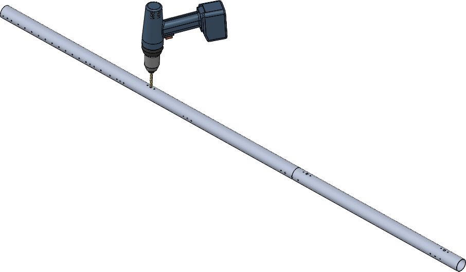
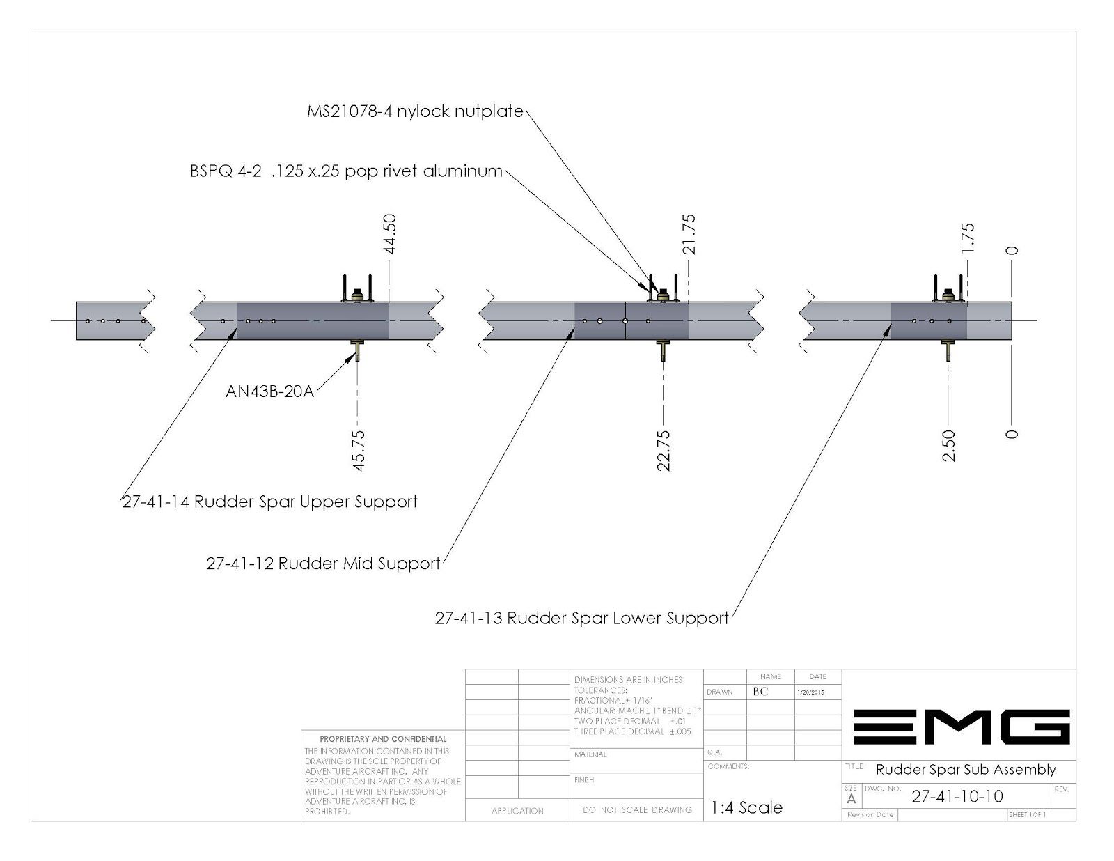
These holes will be located between the 2 holes that are used to attach the Nylock nut plates to the spar.
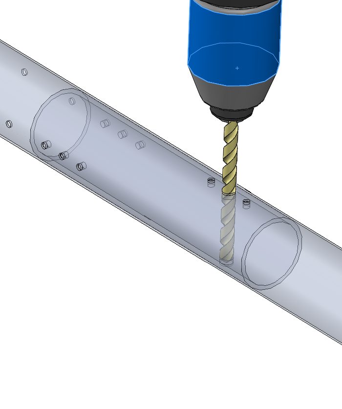
We will enlarge these holes on the rear side of the spar to 1/4 inch diameter hole. A unibit works well to insure a smooth transition from the 1/8” hole to a 1.4” dia hole. If you do use a unibit insure that you DO NOT enlarge the hole bigger than 1/4”
We will be drilling out the aft side of the spar where the nut plate attaches only. Drill all 3 eye-bolt locations as shown on drawing 27-41-10-10
Reference Drawing 27-41-10-10
Rudder Spar Upper Support
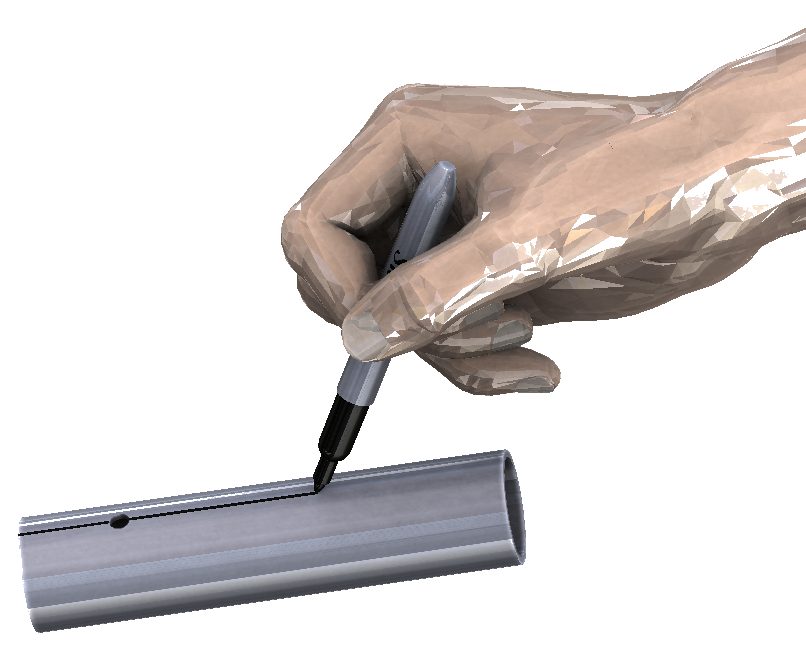
There is one hole drilled in rudder spar upper support tube.. Using a sharpie or magic marker draw a line parallel with the tube through the center of the existing hole that is drilled for the rudder hinge eye-bolts.
Insert the rudder spar upper support inside of the rudder spar and using the line as an alignment guide, call line the upper support with the lower support bolt hole.
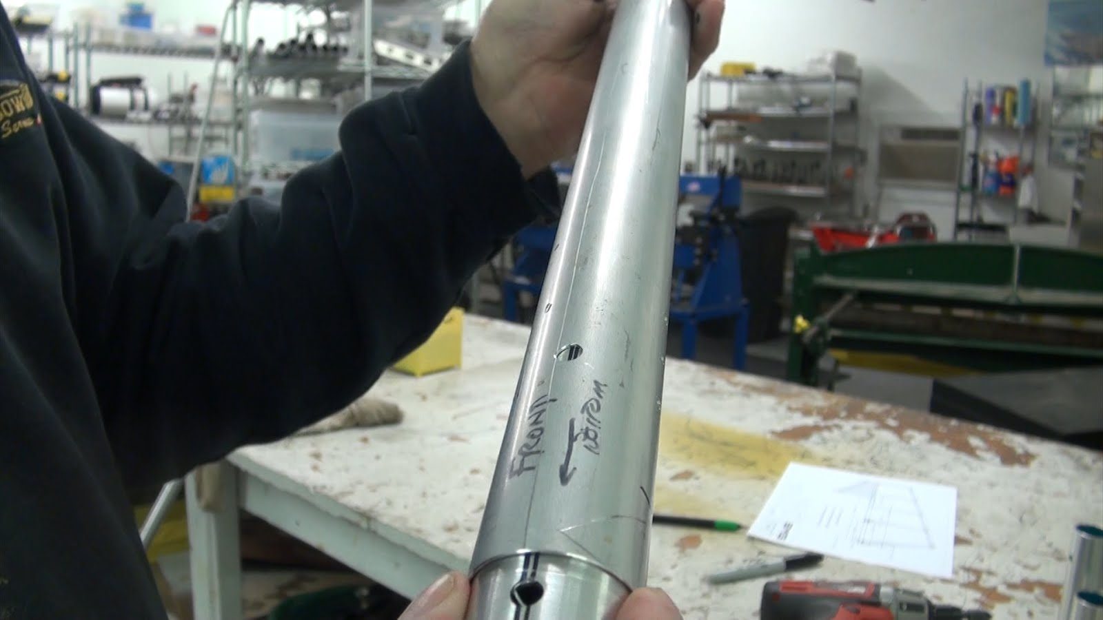
Push the support using a stick or a another smaller tube up to the upper hole until the line on the tube can be seen through the spar eye-bolt hole.
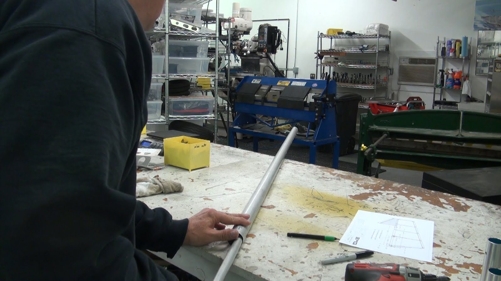
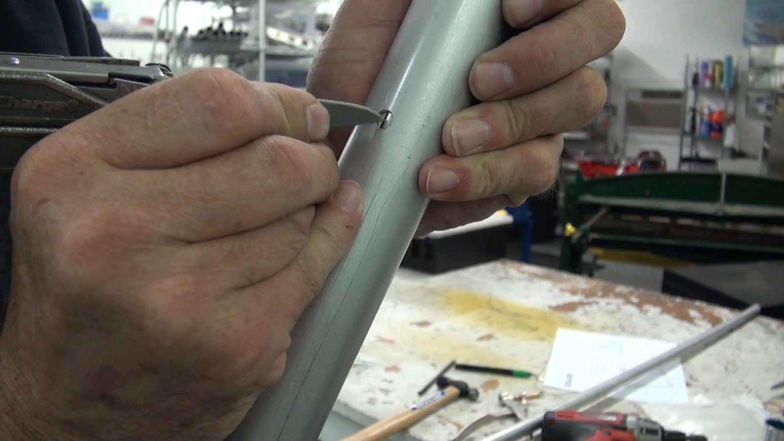
If necessary rotate the tube using a pick or a knife until the alignment line is in the center of the bolt hole.
Next, simply push the insert in until the bolt holes are closely aligned.
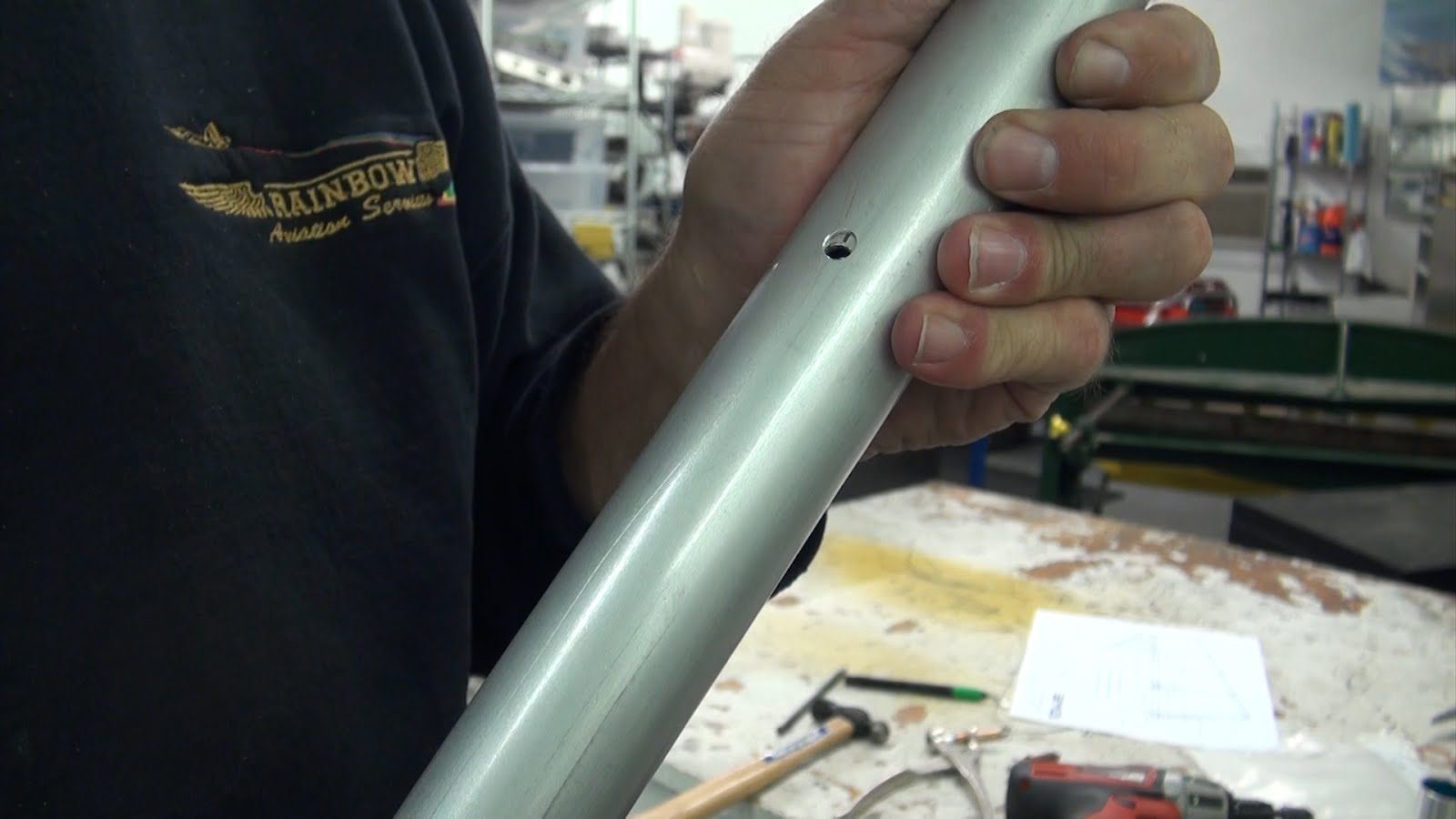
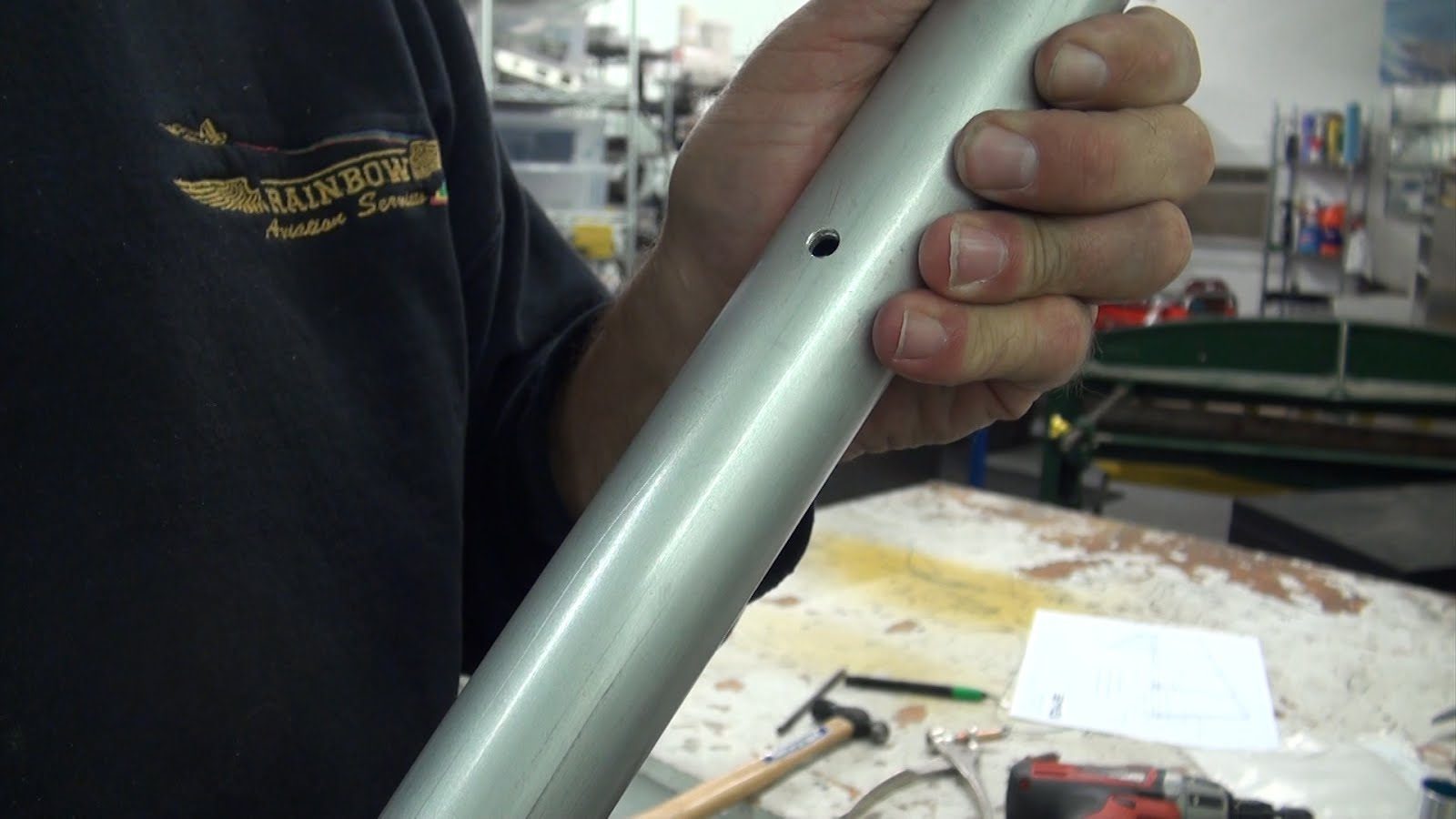
Next an alignment punch can be inserted to further align the bolt holes.
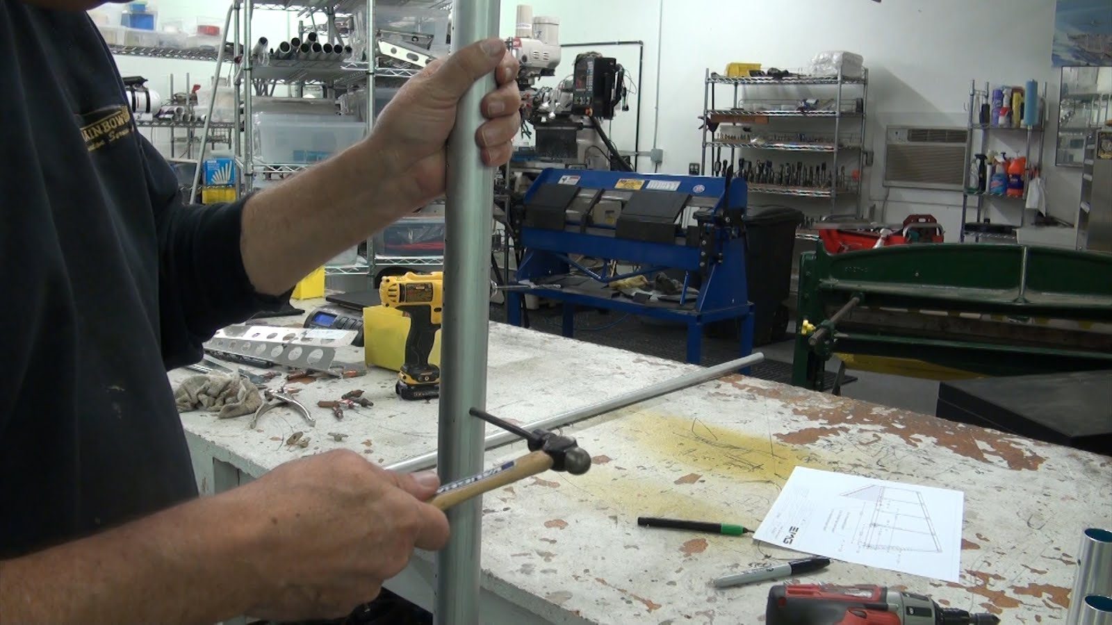
Now remove the punch and using the internal support as a guide drill completely through the rudder spar. this will ensure that the rudder spar and the internal support bolt holes are perfectly aligned.
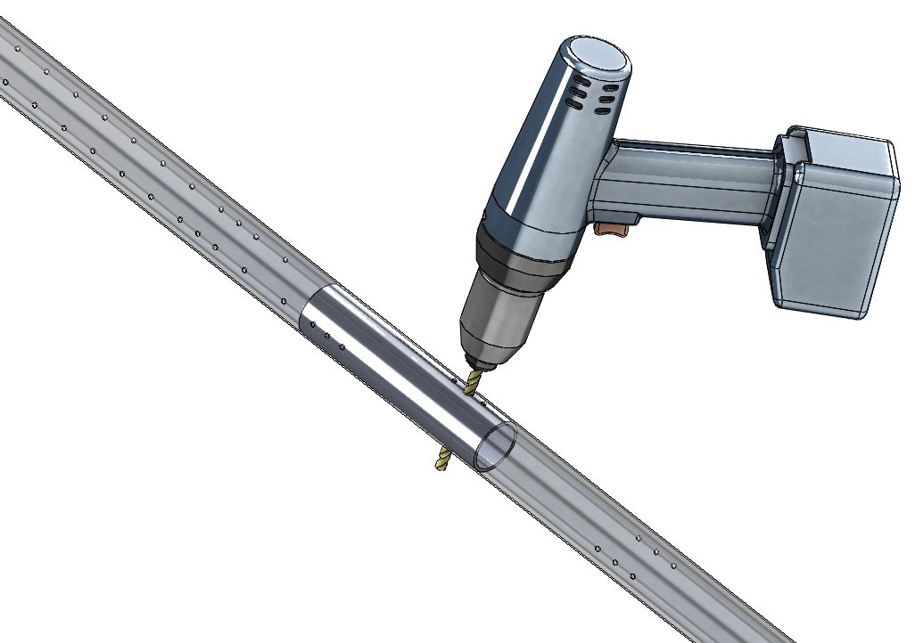
With an alignment pin or the eye-bolt holding the alignment of the internal support tube drill the nut plate holes using the pre-drilled spar as a guide.
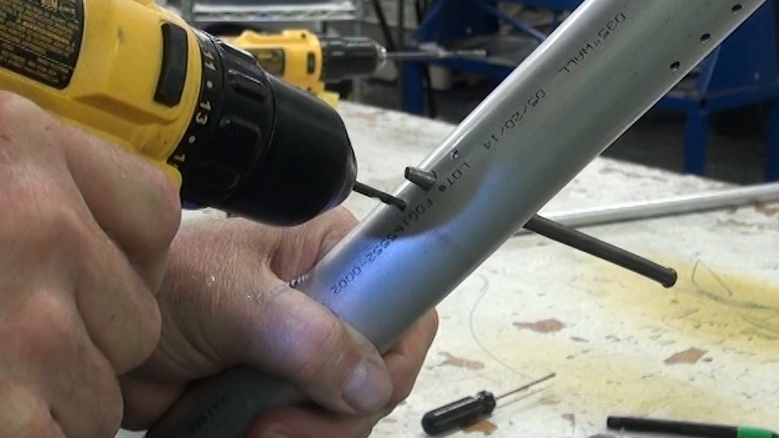
Once the nut plate mounting holes have been drilled you can install a cleco to hold the internal support tube in place while you remove the alignment pin.
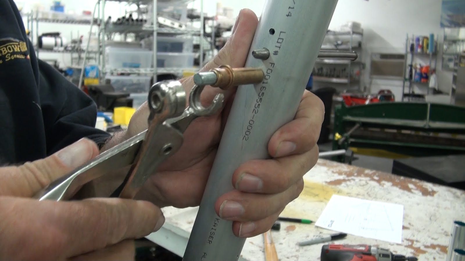
And you are now ready to install the nut plates.
Nut Plate Installation
The nut plates that were going to install, the MS21078-4 Nylock Nut-plate has holes pre-drilled into the mounting legs that are drilled with a number 40 drill bit.
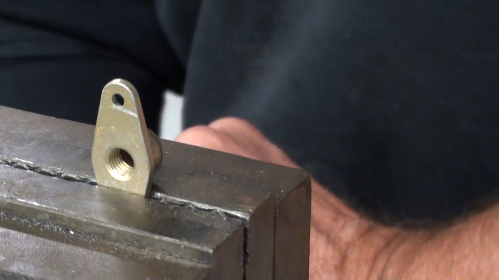
We will need to drill out each of the legs to accept a 1/8 inch rivet using a number 30 drill bit. You will need to place the nut plate in a vice with smooth jaws to hold it during the drilling process.
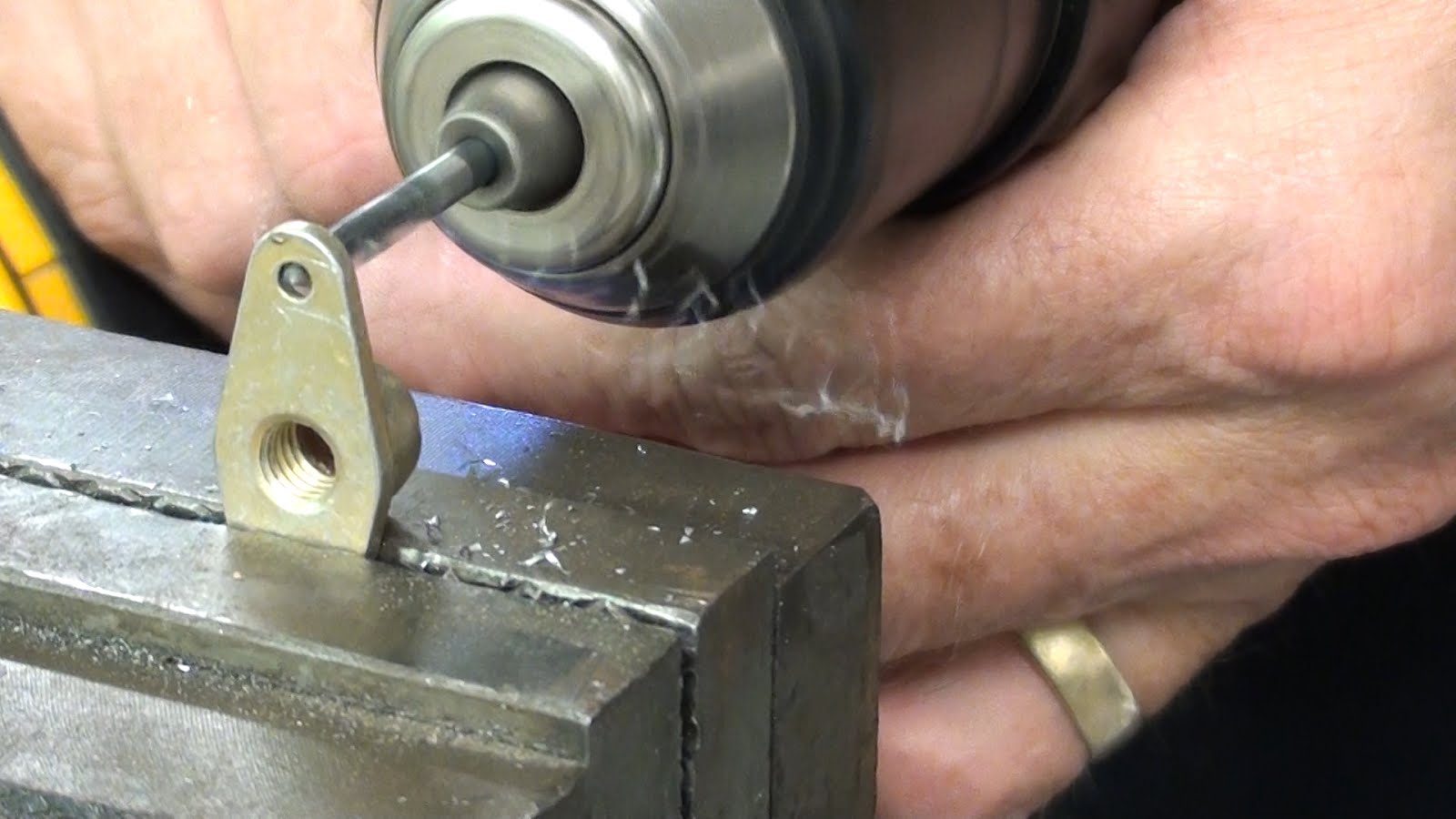
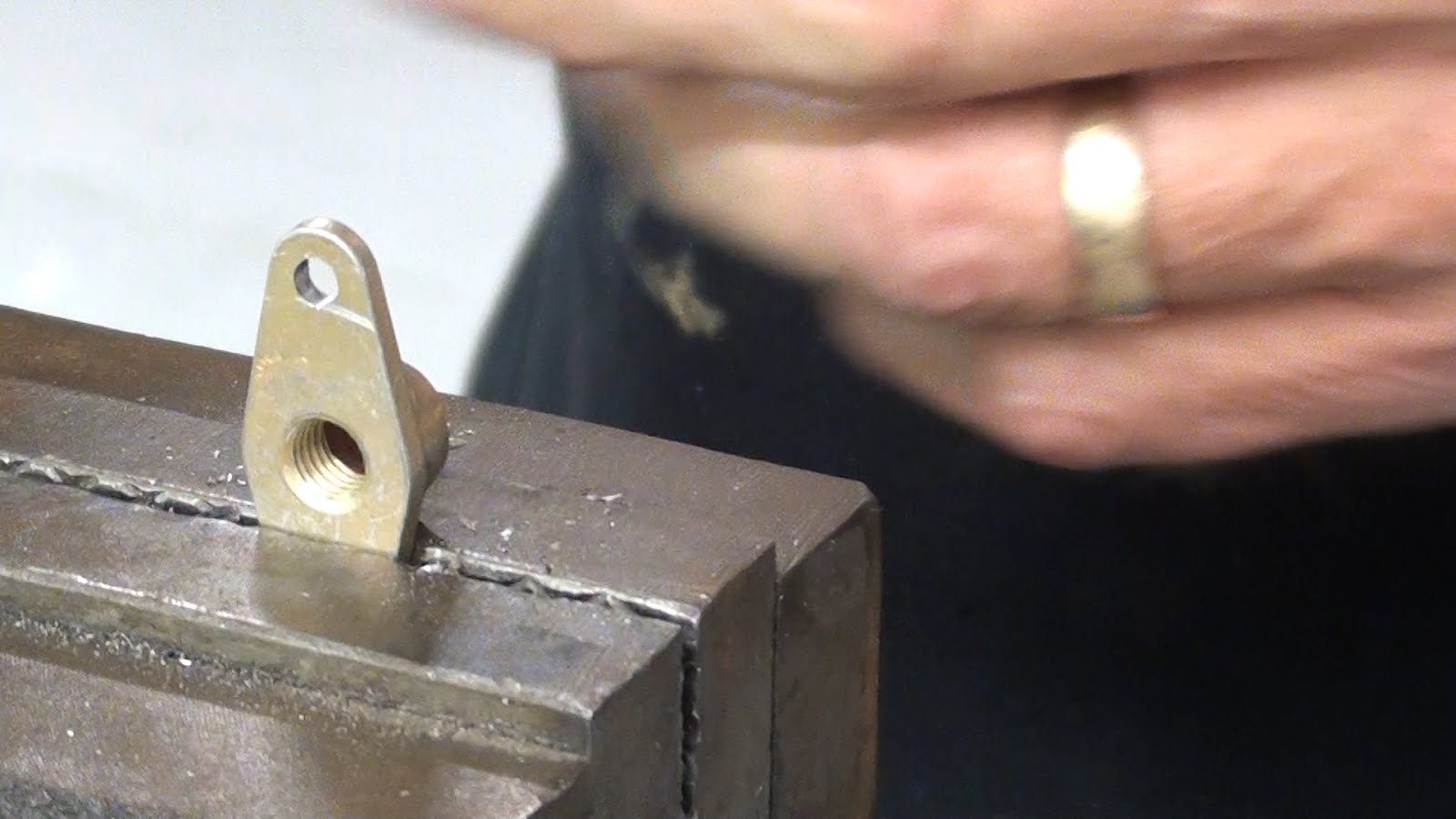
Temporarily insert AN 4 bolt or the eye-bolt for the hinge through the rudder spar with the eye and of the bolt facing forward and the threaded portion of the bolt facing aft.
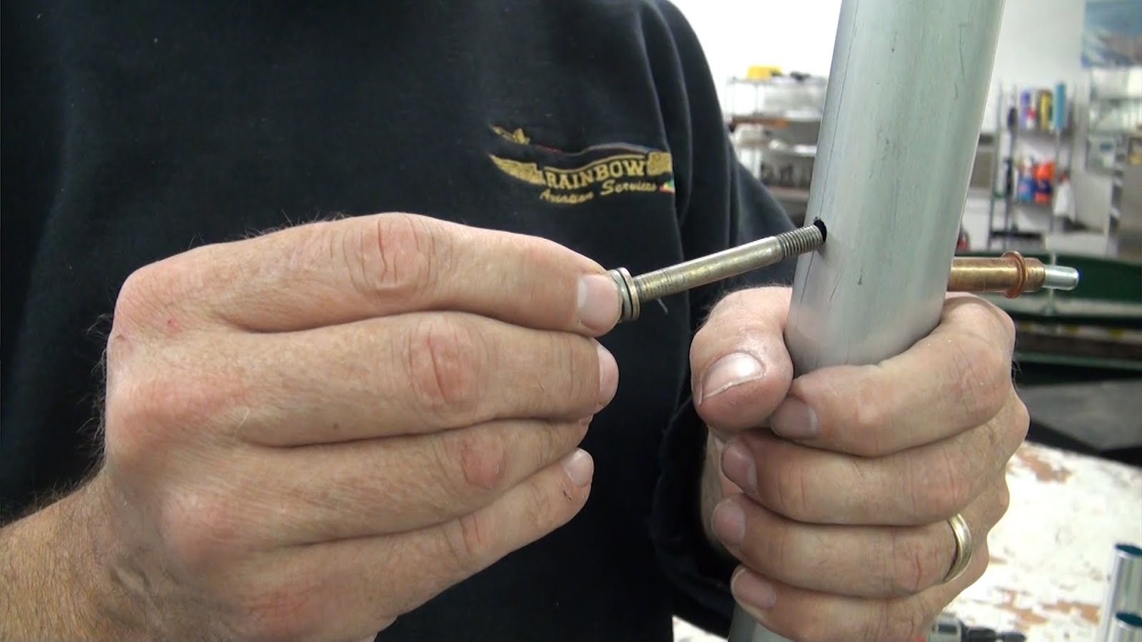
Next spin a nut plate on to the eye bolt. In this case there is no need to insert the threaded portion of the bolt into the Nylock region of the nut plate, simply thread the bolt in far enough until it bottoms out on the nylon portion of the nut plate.
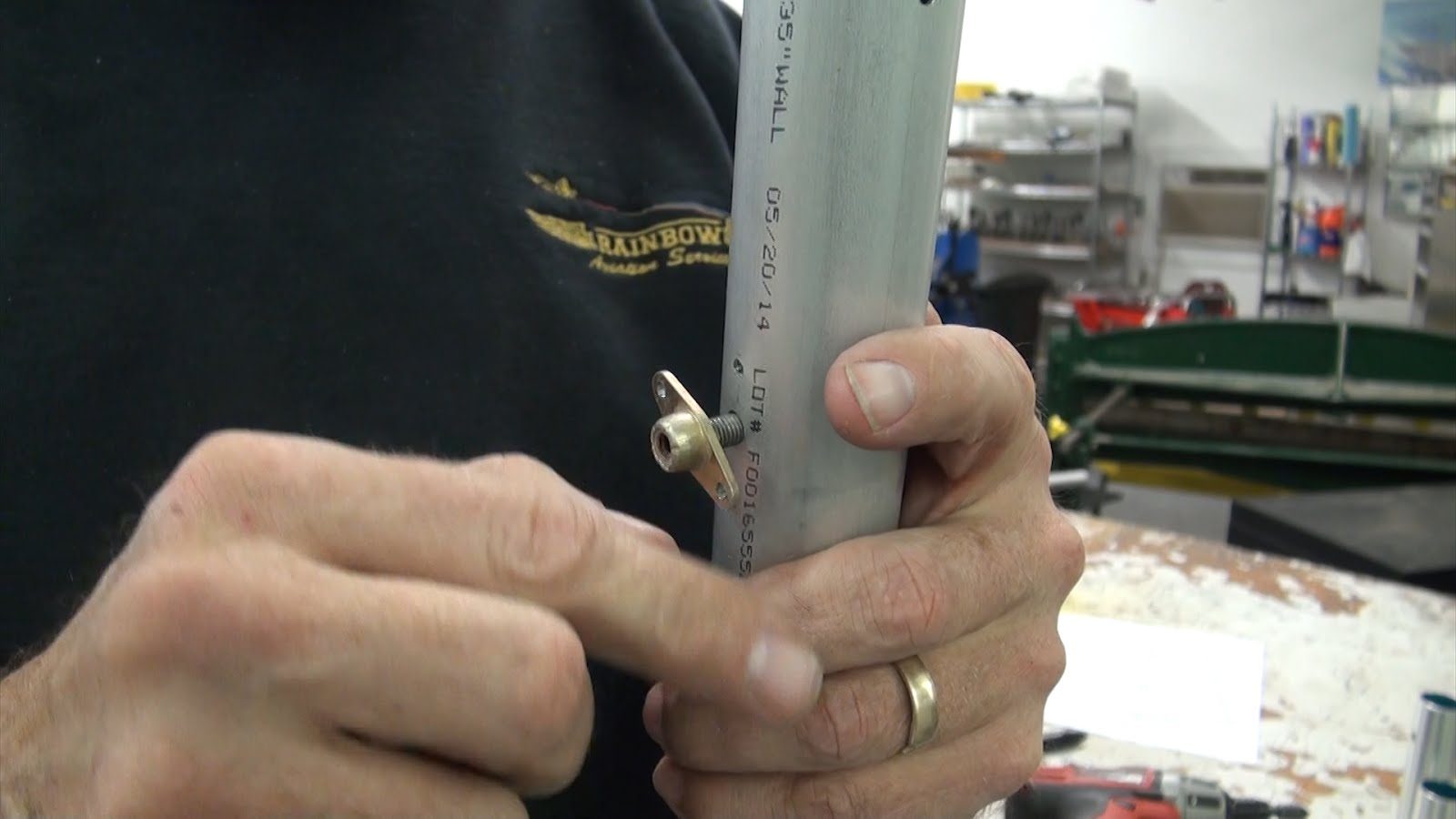
Now cleco one leg of the nut plate to the spar.
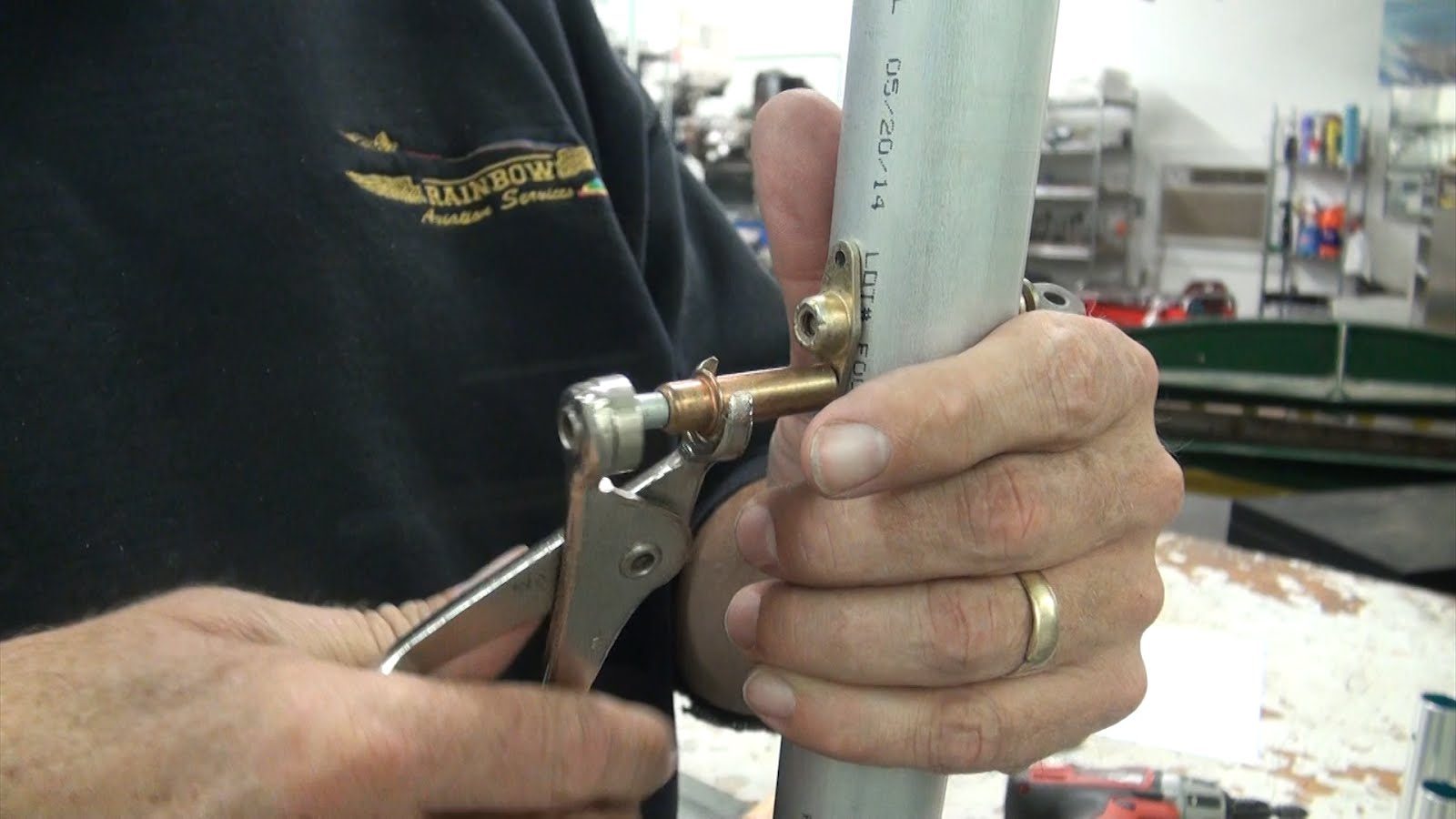
Using a BSPQ 4-4 .125 x.5 aluminum pop rivet secure the nut plate to the spar.
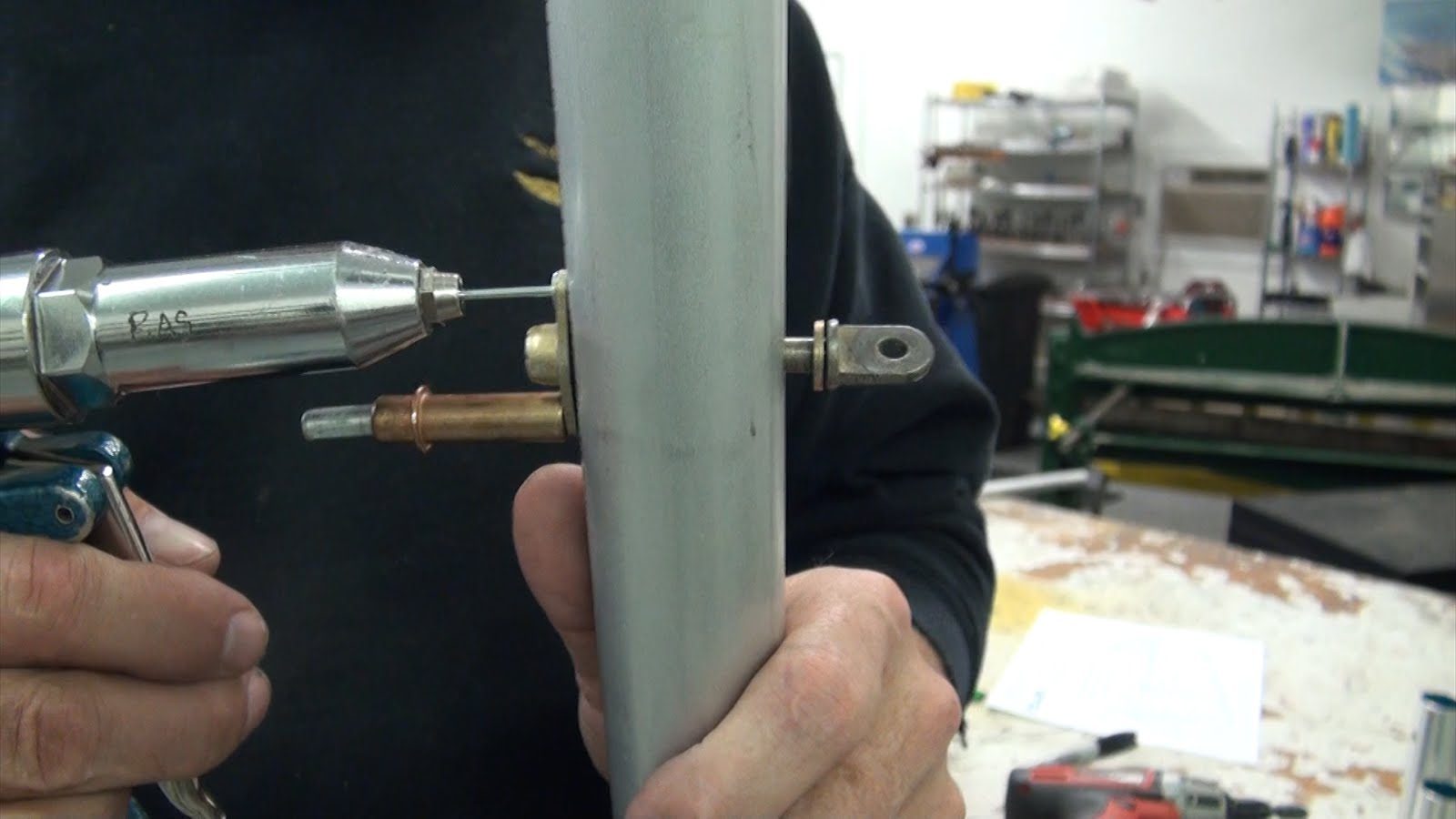
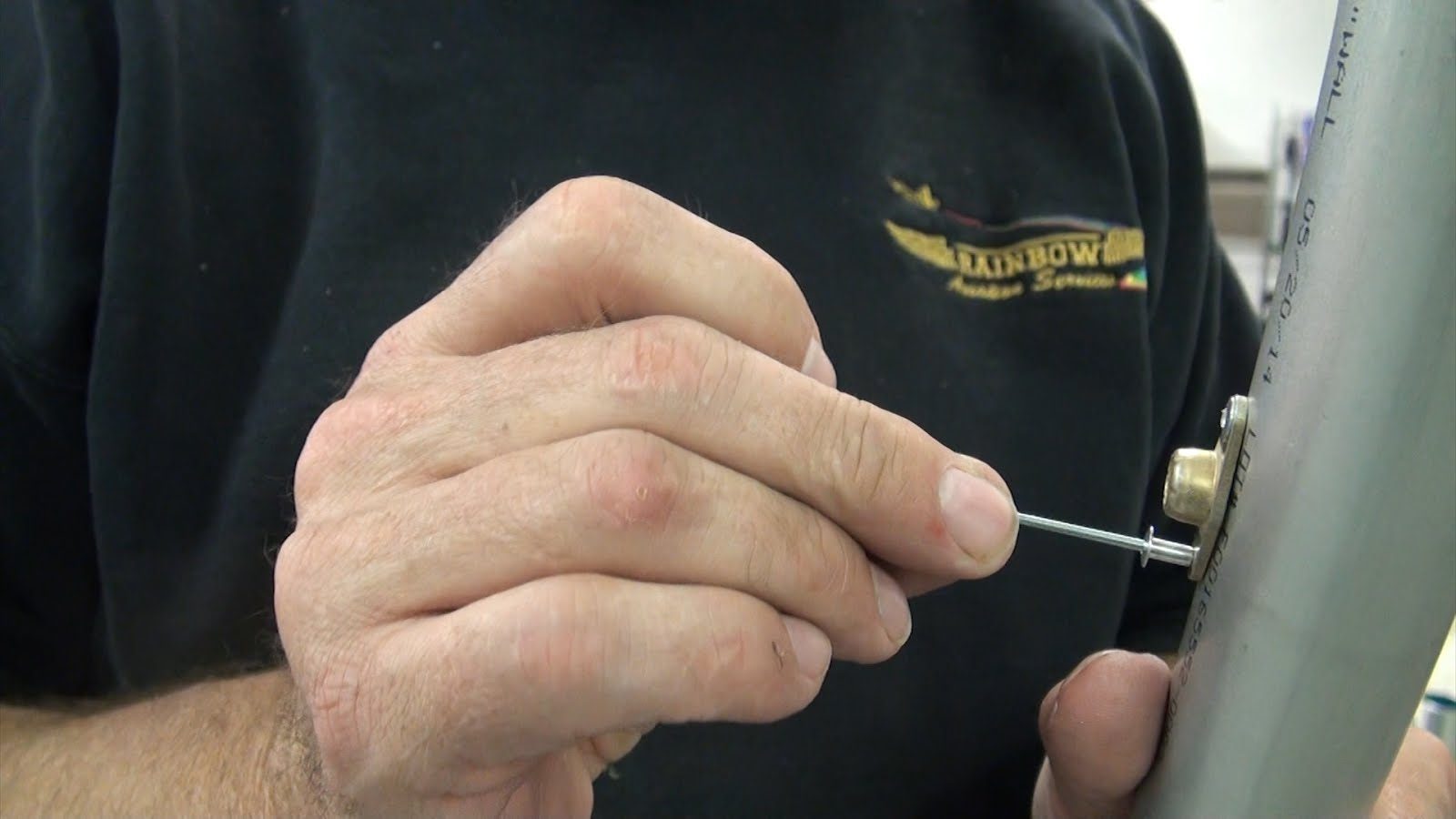
Remove the cleco and install the other rivet in the other leg of the nut plate.
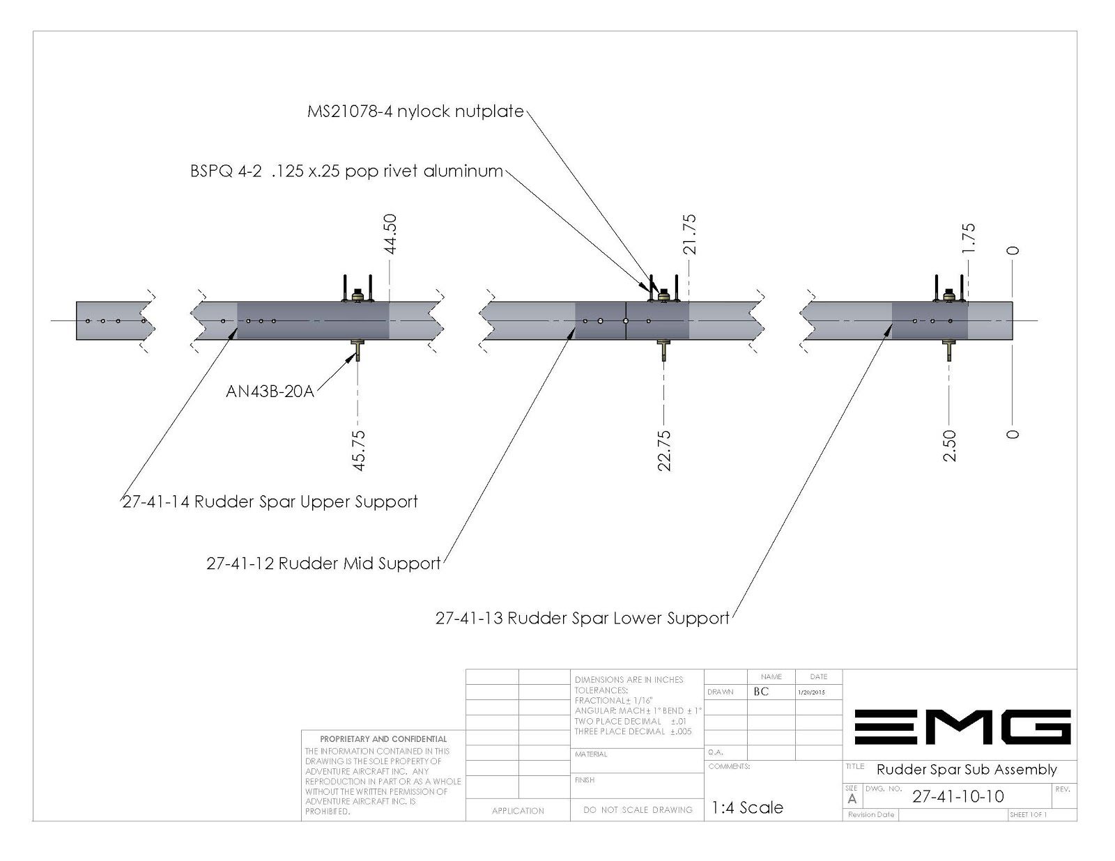
27-41-12 Rudder Spar Mid Support
Duplicate all of the procedures that were used in the installation of the upper support. The rudder spar mid support needs to be installed before the rudder spar lower support can be installed.
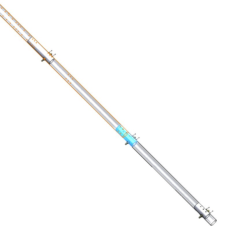
27-41-13 Rudder Spar Lower Support
Duplicate all of the procedures that we just used in installation of the upper and mid supports for the lower support as well.
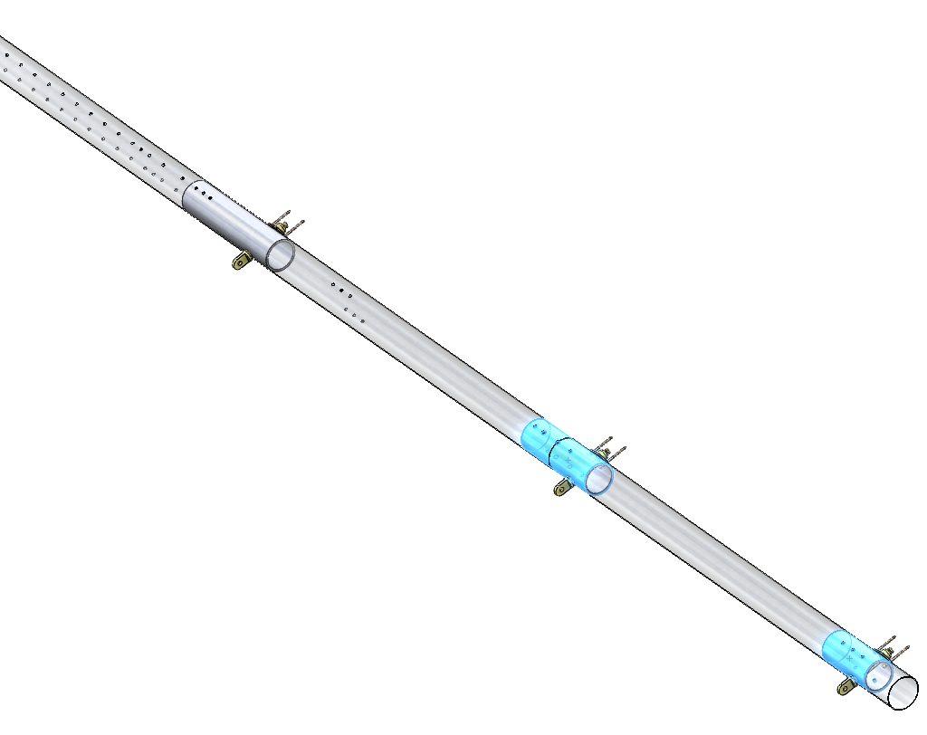
Drilling Rib Attachment Holes
Now that each one of the spar support inserts have been installed into the rudder spar we need to drill the remaining holes on each side of the spar using the predrilled holes in the rudder spar as guides. Use a number 30 drill bit to drill each of the remaining holes. There will be 3 holes on either side of the upper support. There will be 4 holes in either side of the mid support. And there will be 3 holes total on the lower support on either side
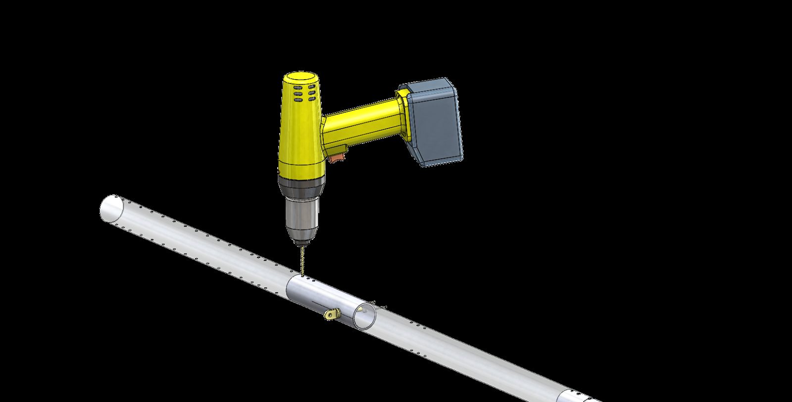
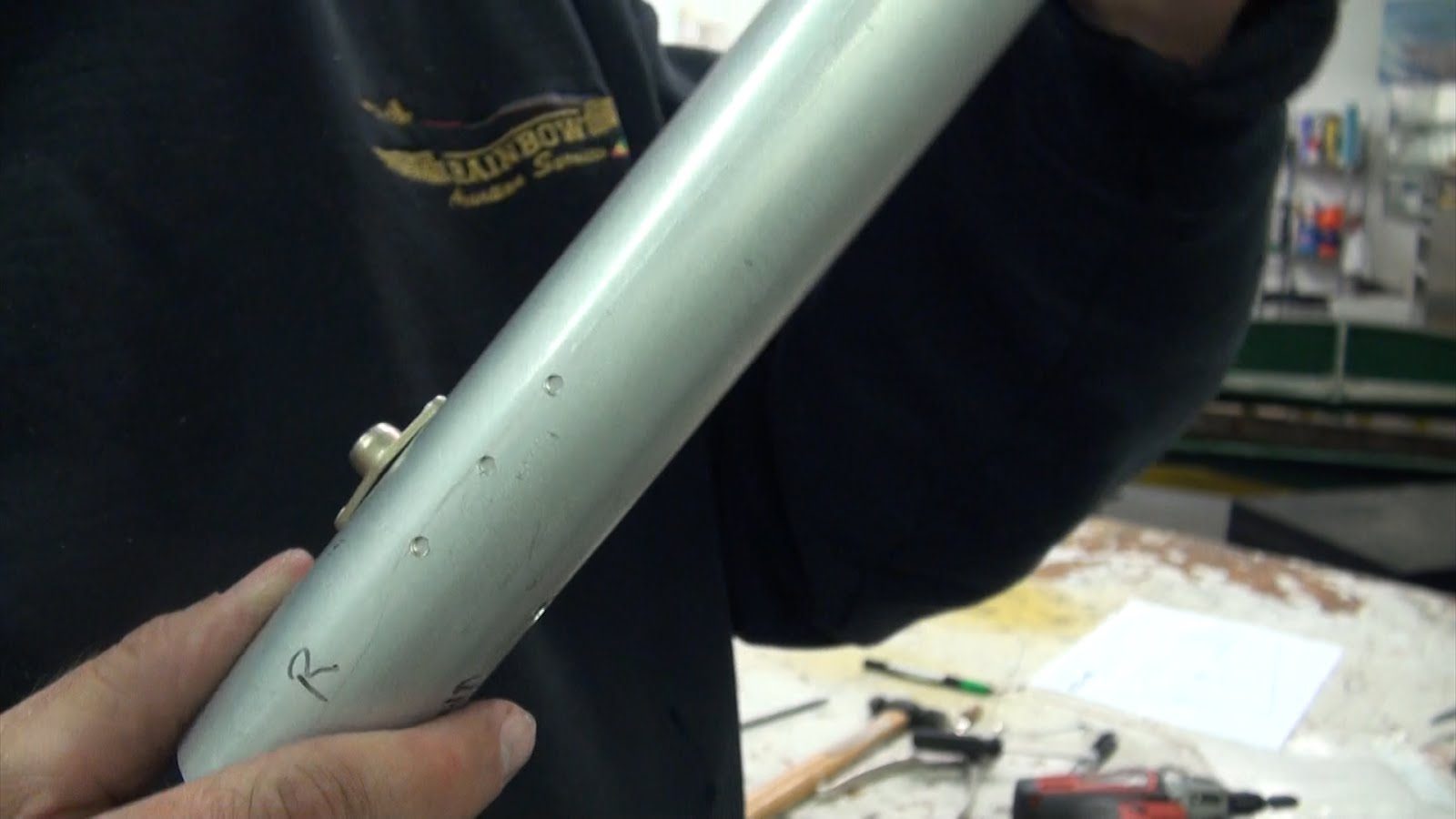
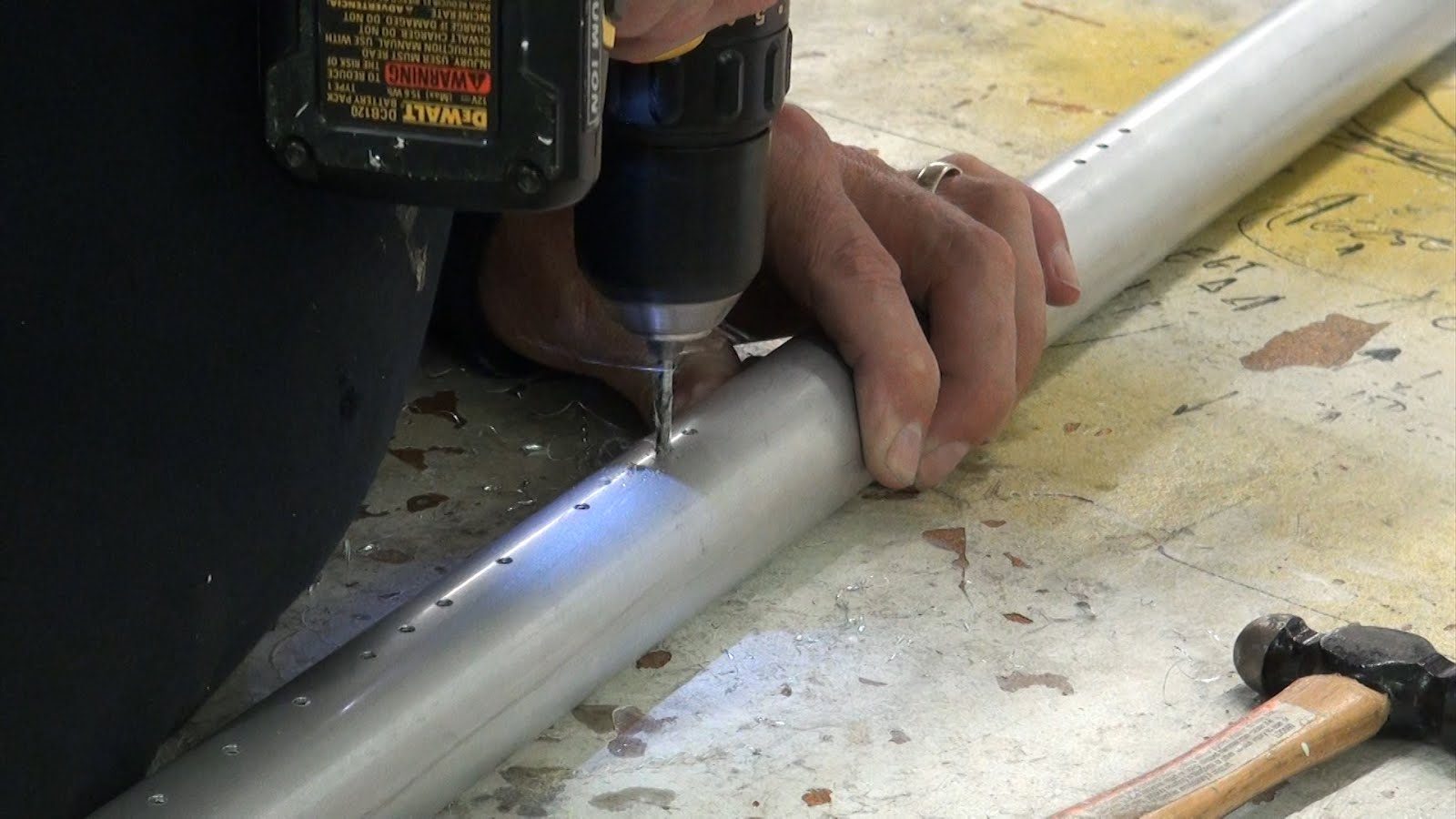
De-burring Spar Sub-assembly
Any of the holes in the completed spar sub-assembly should be de-burred at this time. You may use a slow spinning cordless drill for de-burring with a countersink attachment.
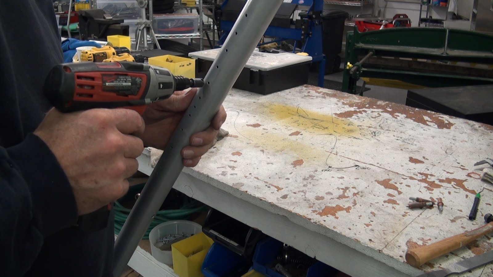
Be careful not to countersink any of the holes.
The de-burring process should be used for only removing any burrs that may interfere with the installation of any of the other sheet-metal parts that will be attached to the rudder spar. Holes that do not have any burrs on them do not need to be de-burred. When you are finished with the de-burring process running your hand slowly over the finished holes will easily identify any holes that still need to be de-burred.
Caution: Aluminum can have a very sharp edges that can cut your hands..
Trimming Upper Spar
The upper spar will interfere with rib number 6 if it is not trimmed.
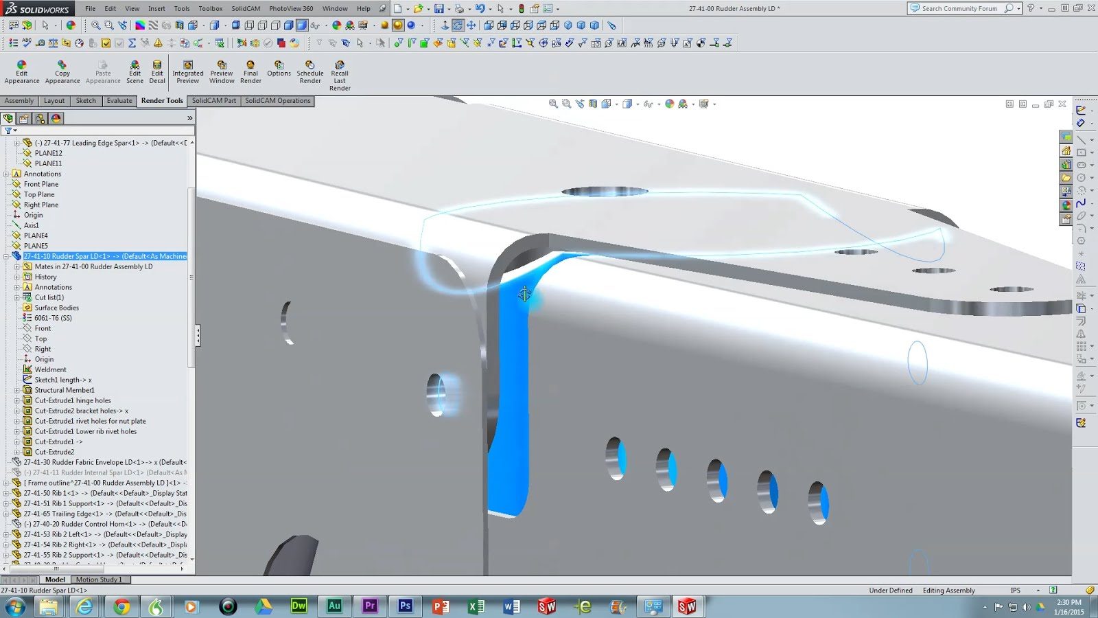
Cut, sand, or file a chamfer or radius on to the top of the rudder spar to provide clearance for rib # 6.
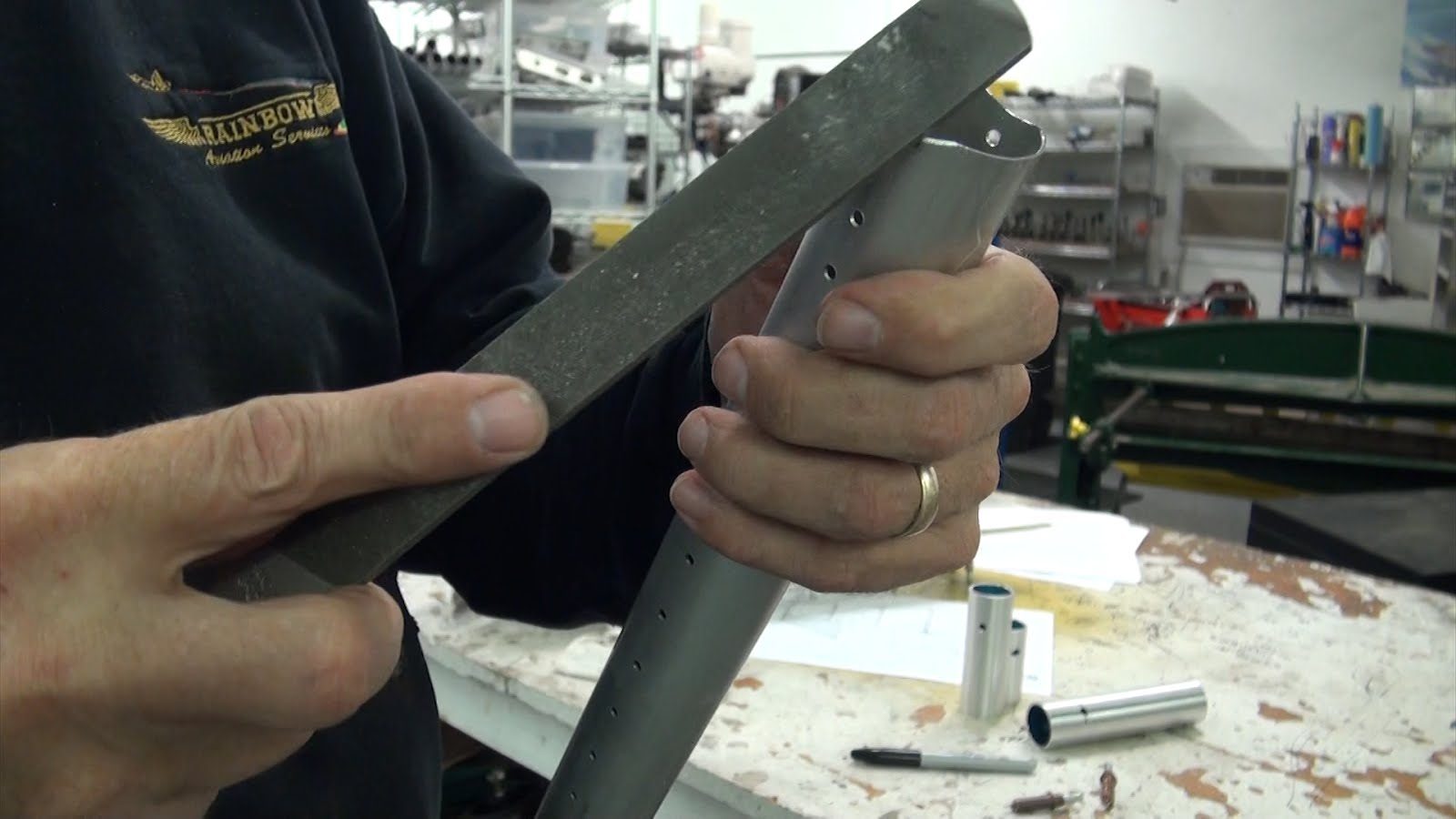
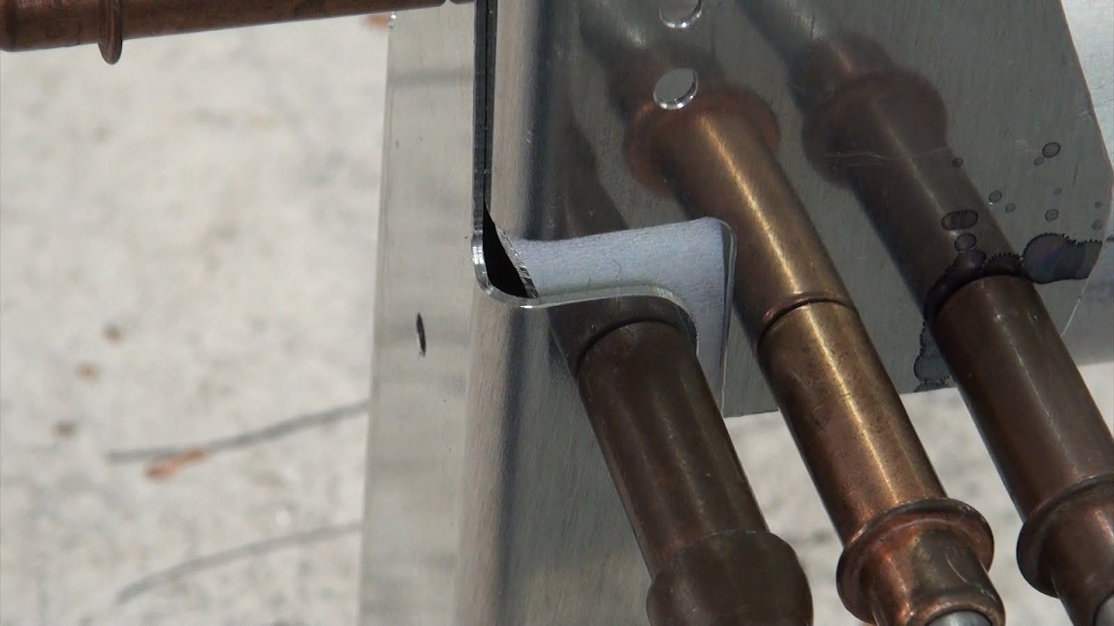
A minimum edge distance from the top rivet hole to the edge of the chamfer should be retained with a .25” dimensions from the center of the rivet hole to the edge of the chamfer.
Rudder Assembly
Rib Identification
Rib #1
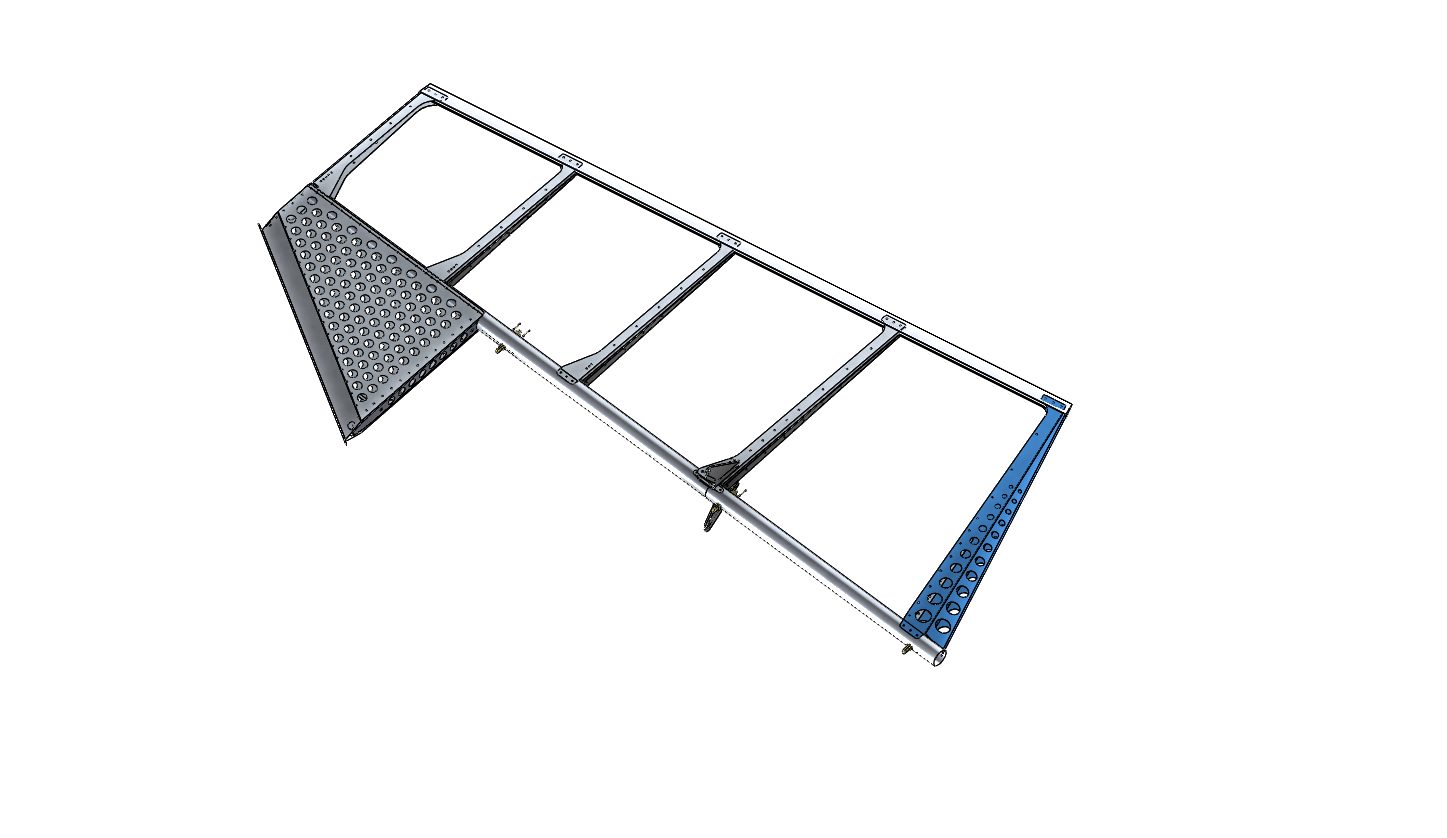
Rib #2
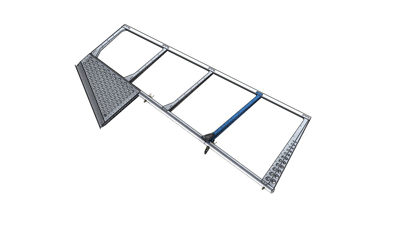
Rib #3
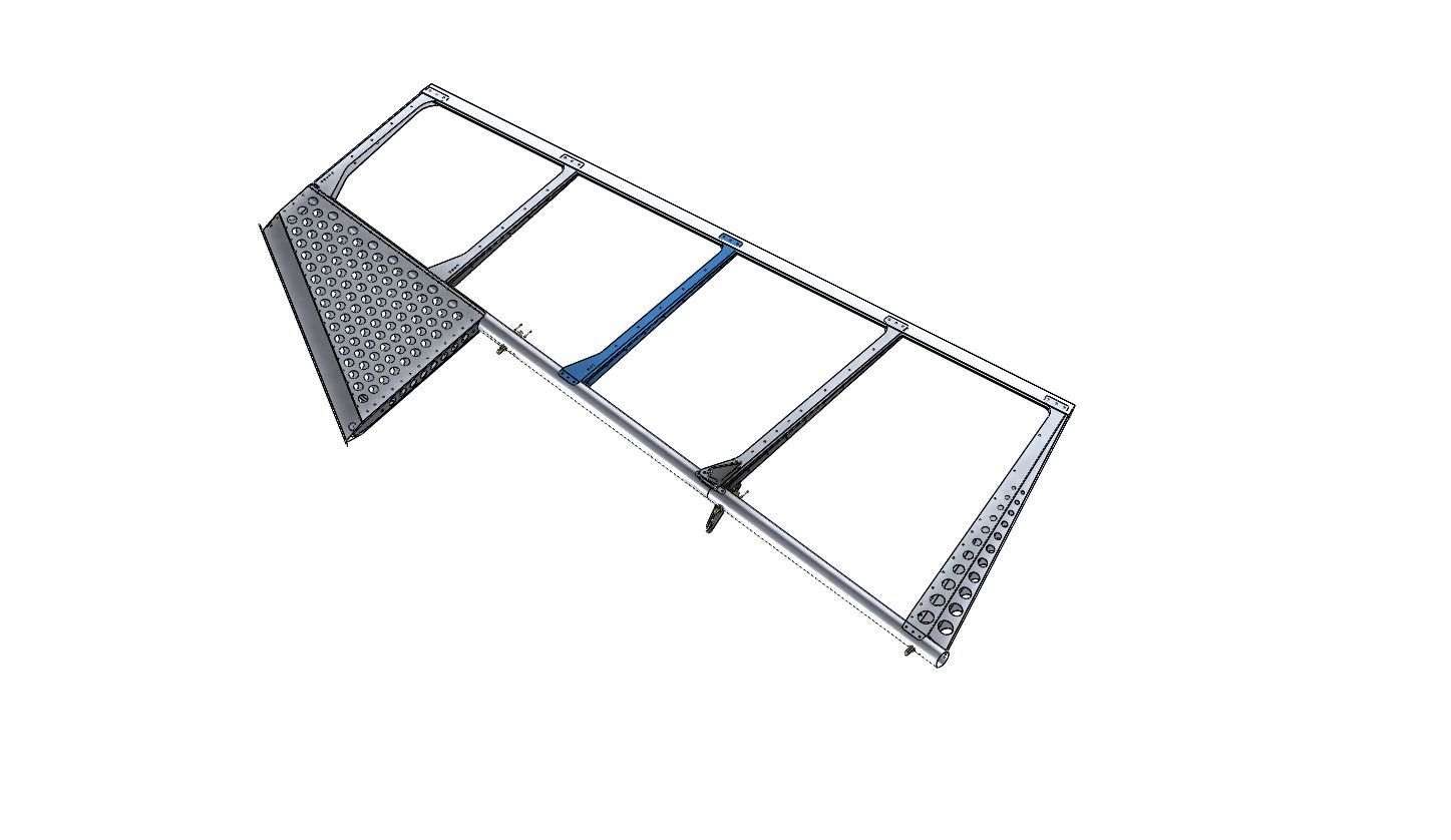
Rib #4
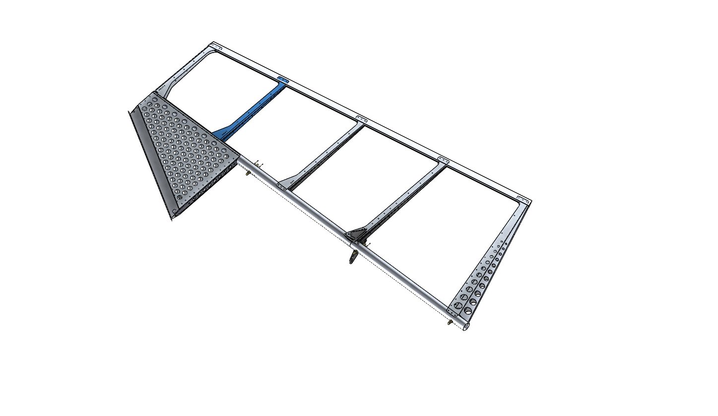
Rib #5
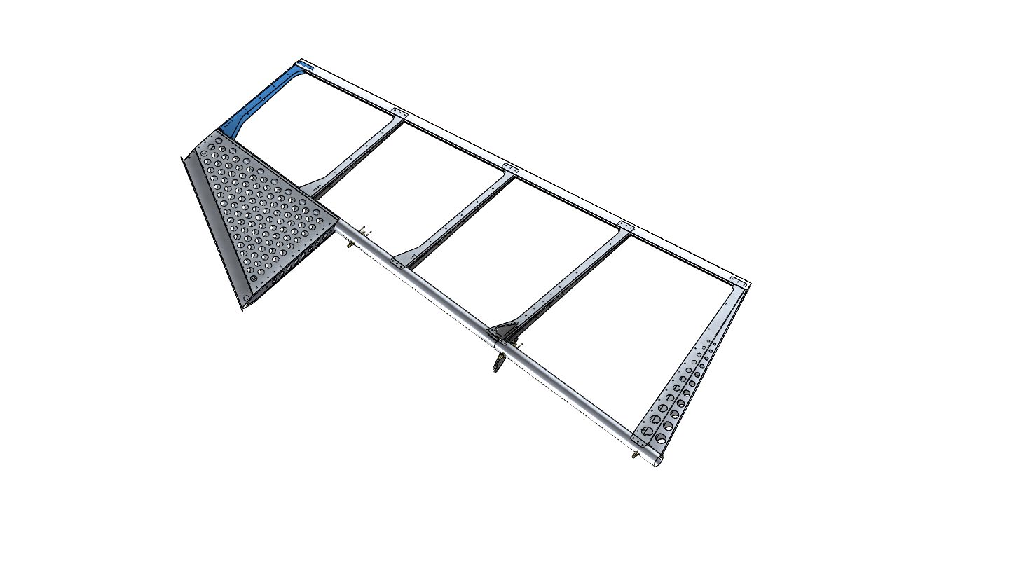
Rib #6
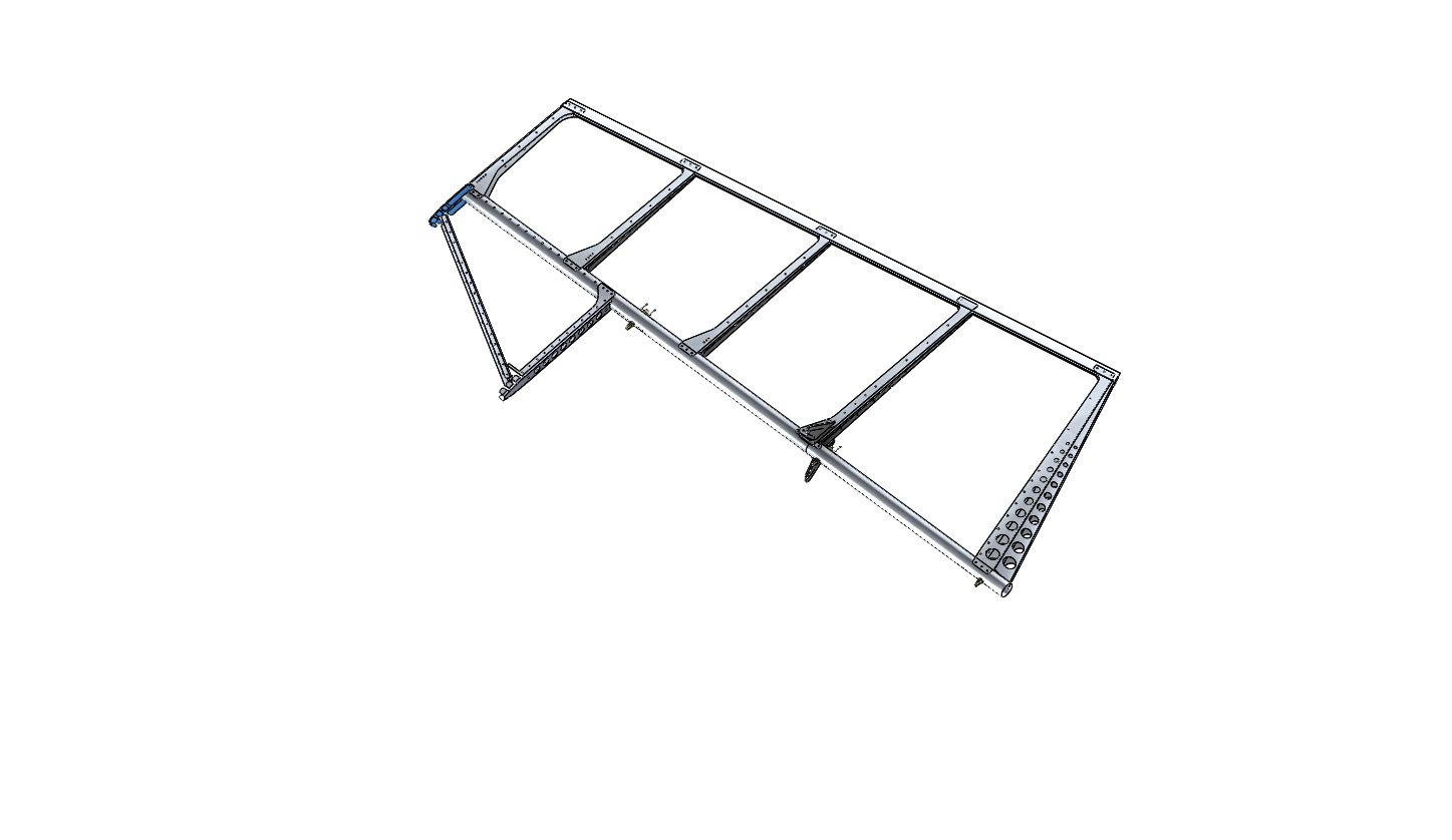
Rib #7
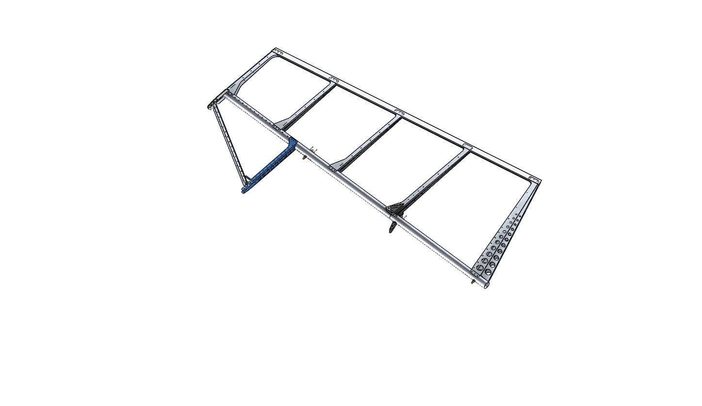
Rib Coding
Rib Numbering System
There are several methods by which we identify each of the ribs.
The 1st of which is the rib numbering system each rib can buy identified by the number of holes drilled in the forward section of the rib
This rib here is rib number 5 and you can see at the forward edge 5 holes drilled horizontally and parallel with the axis of the rib.
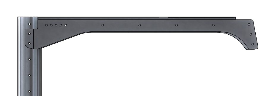
In addition you can see that the left side ribs are longer than the right side ribs. The purpose for this is to offset the rivets in the trailing edge so that they do not interfere with each other during the installation process.
The right side ribs also have the rib numbering system with holes drilled to identify which rib is indicated. However on the right side ribs in addition to being shorter than the left side of the rib identification holes are drilled at an angle.
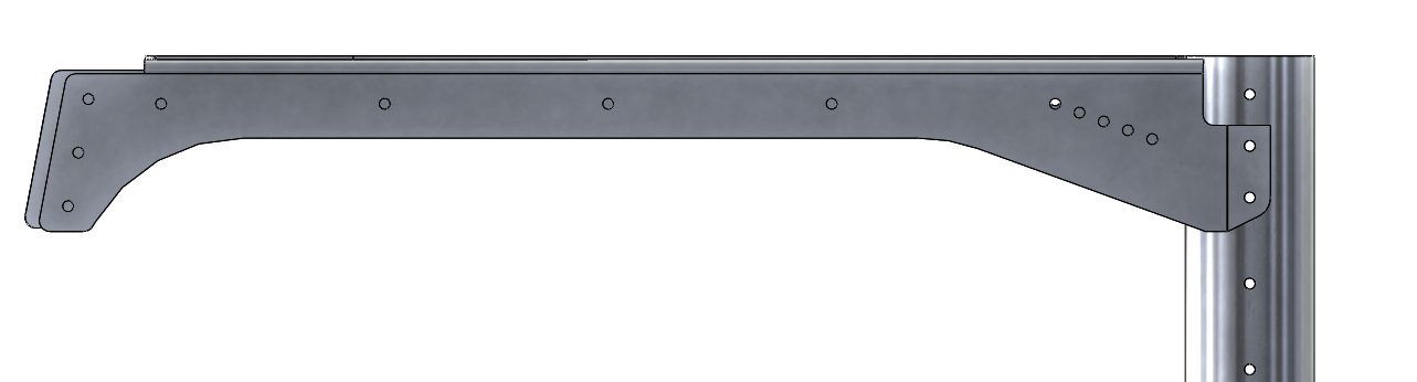
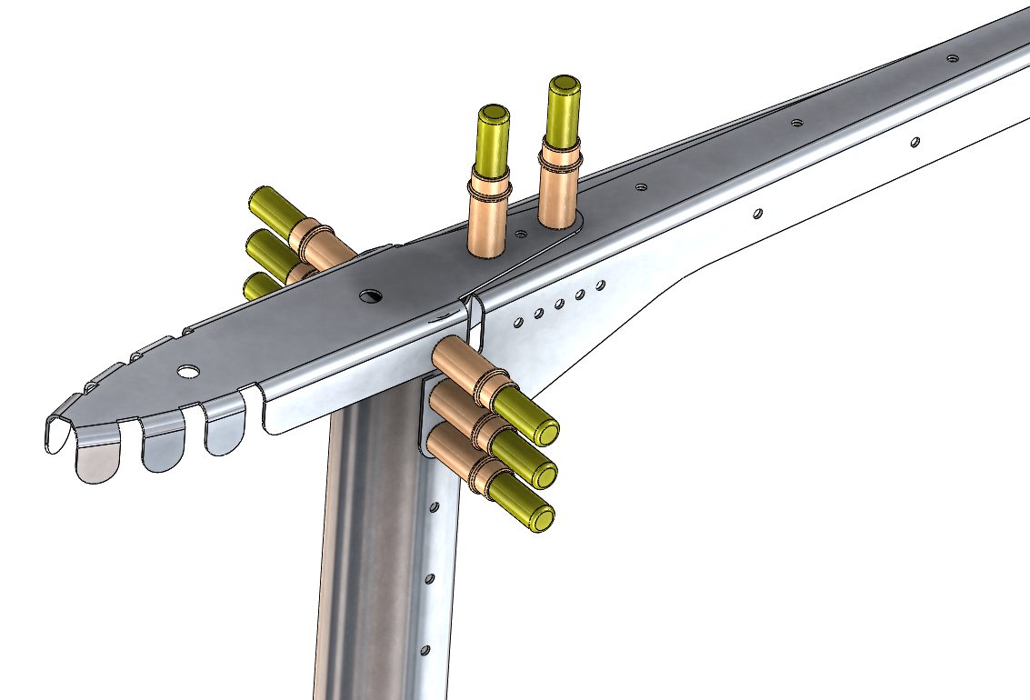
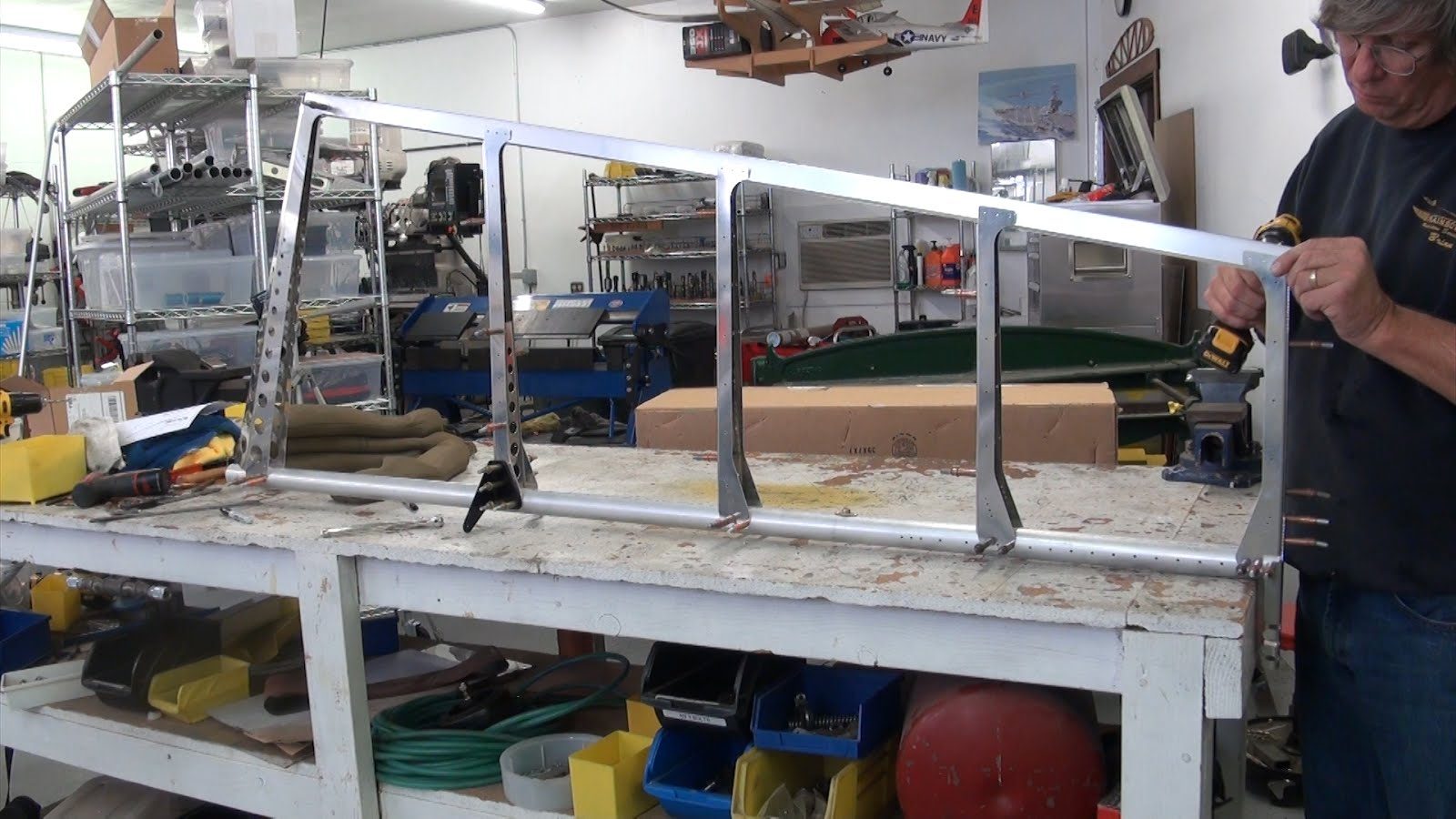
Rib #5 is the 1st set of ribs to be installed on to the spar sub-assembly. Cleco both the left and right tip ribs in place these are p/n 27-41-60 rib number 5 left and p/n 27-41-61 rib # 5 right. The ribs are two-piece ribs that overlap each other. As can be seen in this diagram the left rib overlaps the right rib. All of the ribs during the initial installation will be cleco’d in place and no rivets will be installed until the majority of the structure has been assembled.
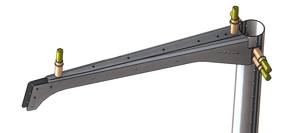
Rib number 6 is the top leading edge rib and intersects with both rib number 5 and the rudder spar subassembly. Cleco in place as shown.
Cleco both left and right rib halves together 27-41-58 rib 4 left and 27-41-59 rib 5 to the main spar with the flanges facing upward. Note the rib overlap orientation.
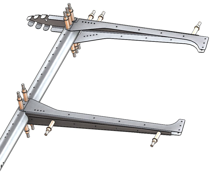
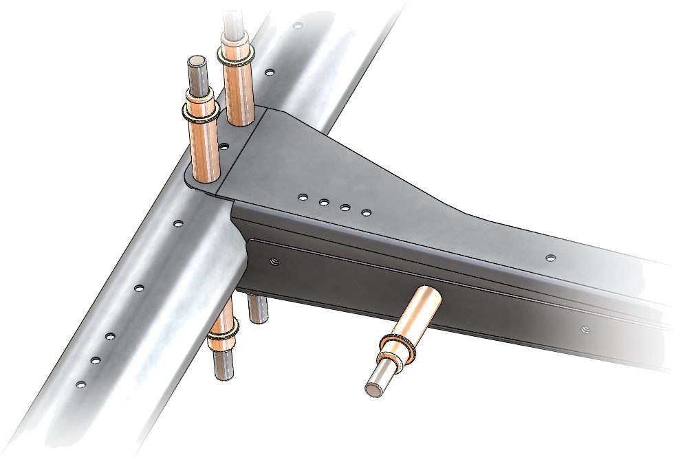
Cleco both left and right rib halves together 27-41-56 rib 3 left and 27-41-57 rib 3 right to the main spar with the flanges facing upward. Note the rib overlap orientation.
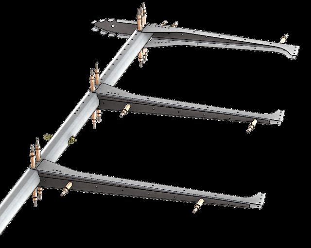
Rib number 1 is a single piece rib that is pre-bent into the shape required for final installation. During the manufacturing process there are 2 tabs on either end of the rib there used for proper alignment in the CNC press brake.
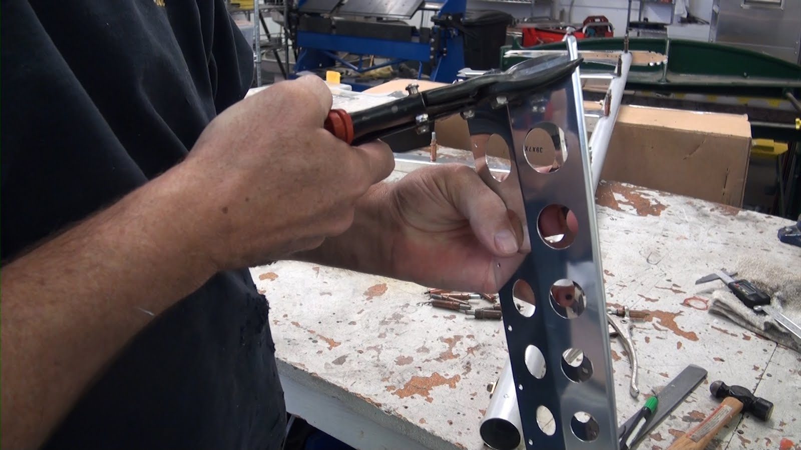
The aft tab can remain in place which will assist in holding the fabric in that location. However the forward tab will interfere with the rudder spar and as such needs to be trimmed from the leading edge bottom V. After cutting the alignment tab you will need to file and deburr the trimmed area. Cleco rib number 1 in place as shown in the diagram.
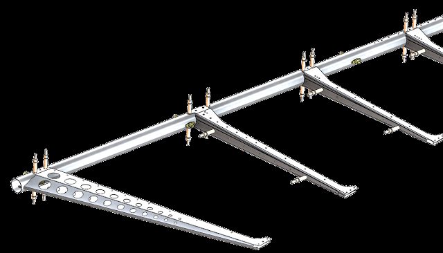
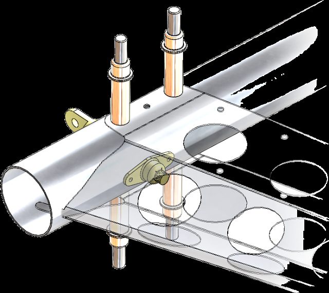
Rib #1 Support 27-41-51
Rib number 1 support ties the 2 legs of rib number 1 together. Cleco the rib support in place as shown in the diagram.
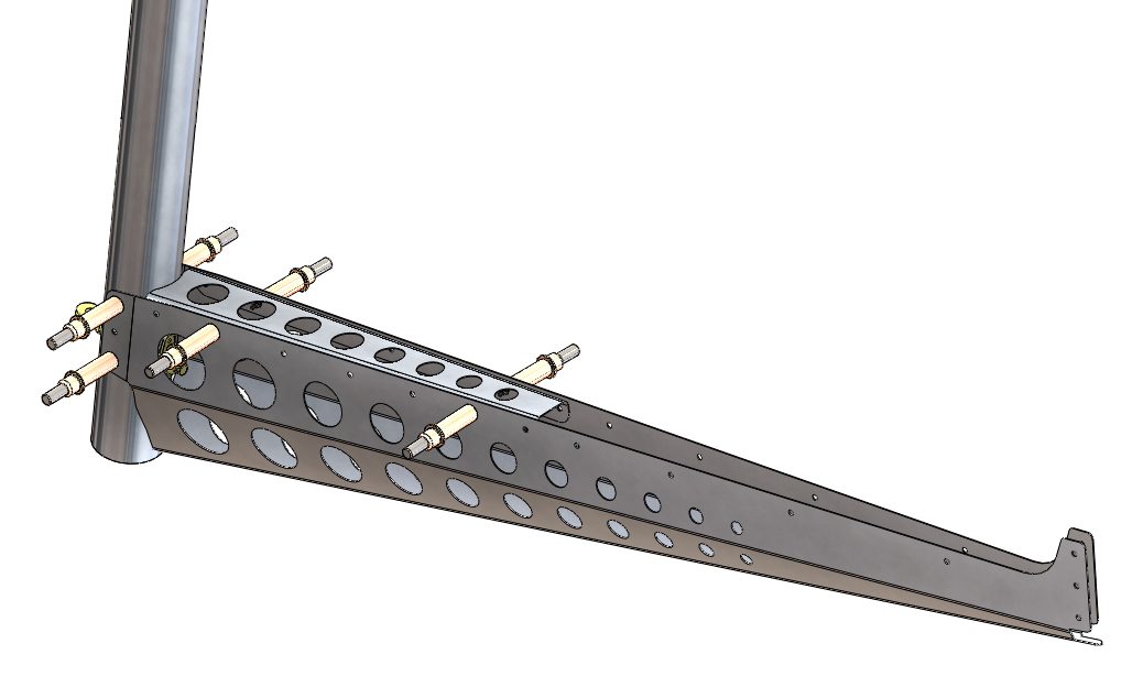
Rib #2 Support 27-41-55
Rib number 2 support ties the 2 legs of rib number 1 together. Cleco the rib support in place as shown in the diagram.
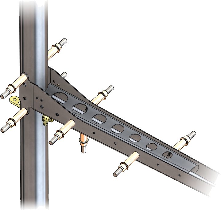
27-40-20 Rudder Control Horn Installation
The rudder control horn attaches to the rib number 2.
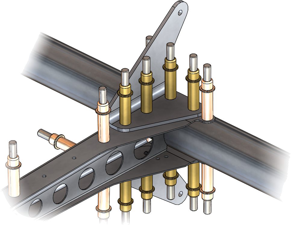
Enlarge the number 30 holes to a 3/16 inch hole using a 3/16 inch drill bit. Start by drilling one of the 2 holes located in the spar sub-assembly. note that this picture was taken before the redesign of rib #2 was modified to include the extra tabs that make it easier to install. The new tabs allow for permanent affixing of the rib to the spar while allowing the control horn to be removed. once rib #2 has been installed drill and affix the additional tabs with a number 30 drill bit and a copper Cleco after drilling.
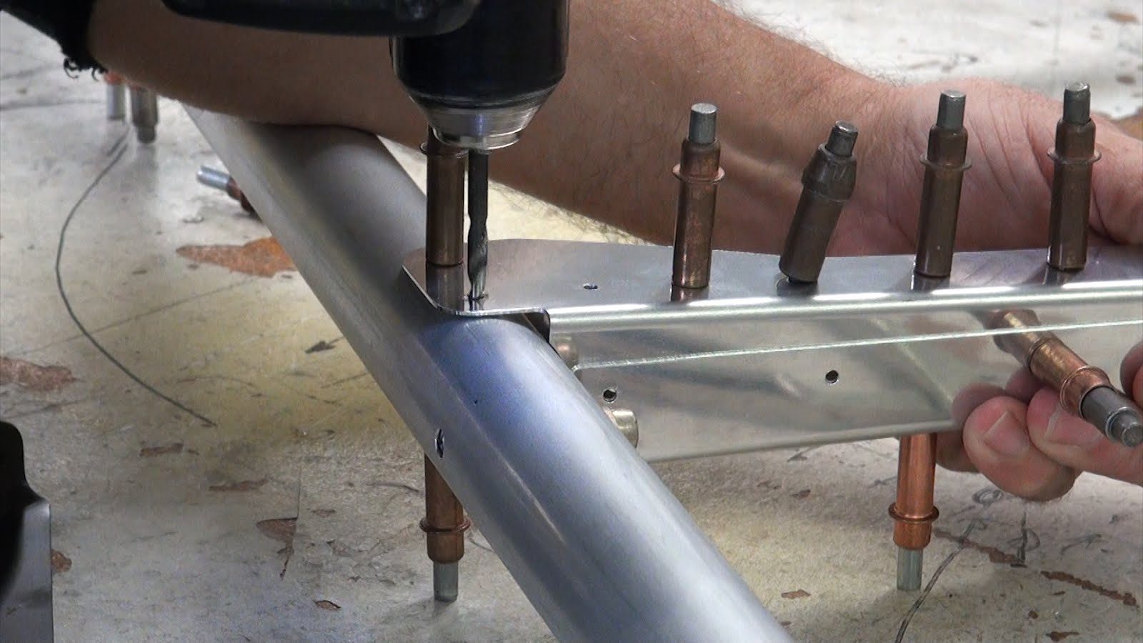
Place the rudder control horn on to the spar using a 3/16 inch brass cleco. Then using the control horn as a drill guide drill the remaining holes in both the spar and rib number 2 and rib number 2 support. Cleco the rudder control horn in place using 3/16 inch brass cleco’s. Duplicate the process for the opposite side.
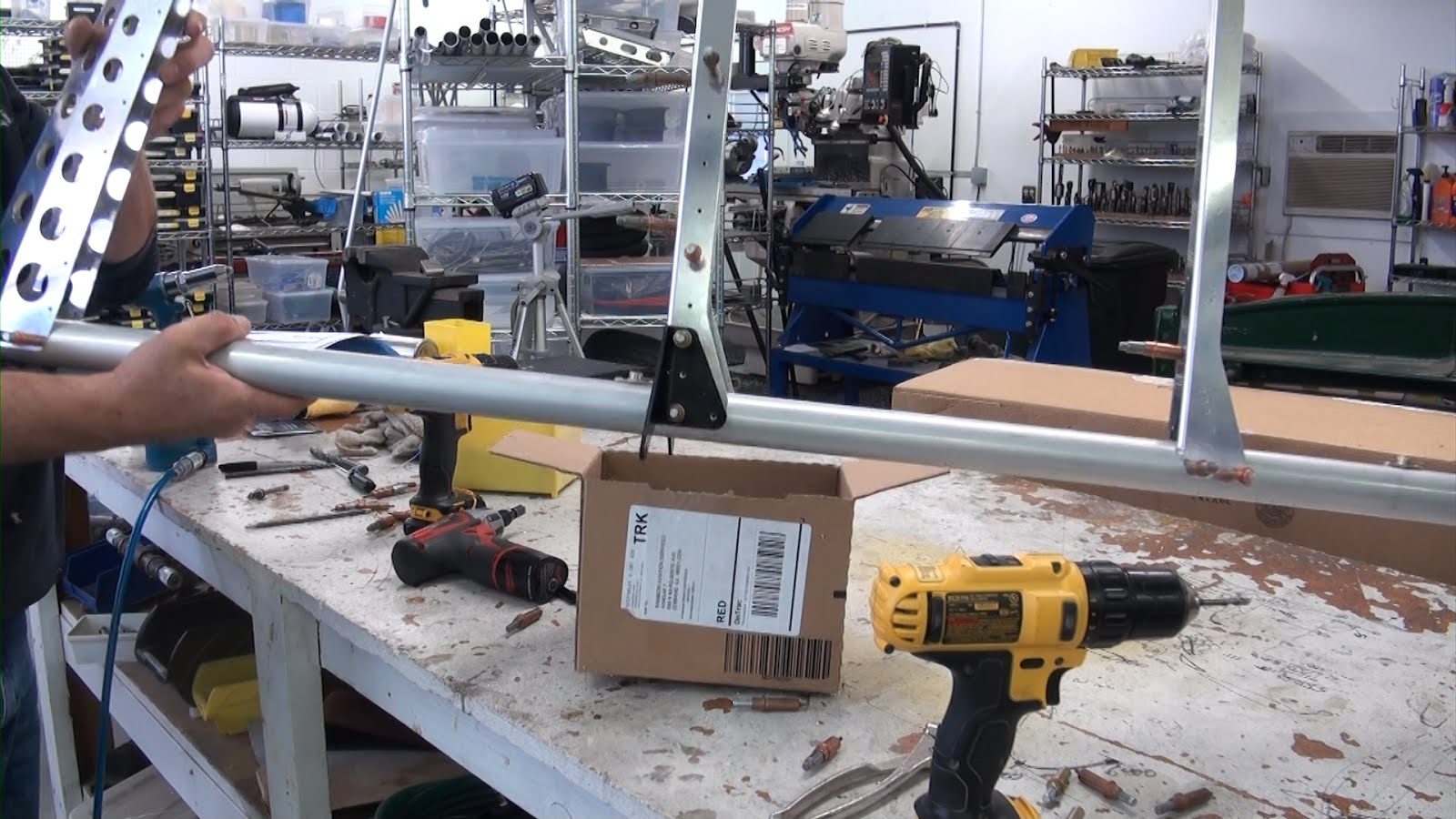
Trailing Edge 27-41-65
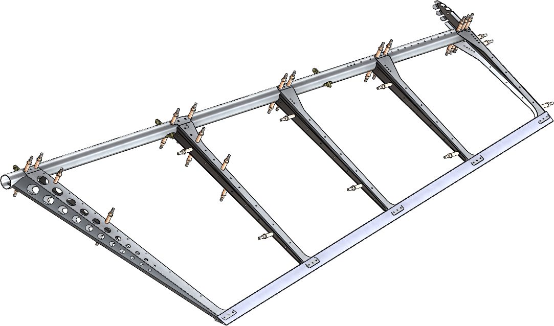
Before we insert the trailing edge into each of the rib locations we need to place the trailing edge material in position on top of the ribs and mark them so that the lower end of the trailing edge is parallel with the lower edge of the number 1 rib.
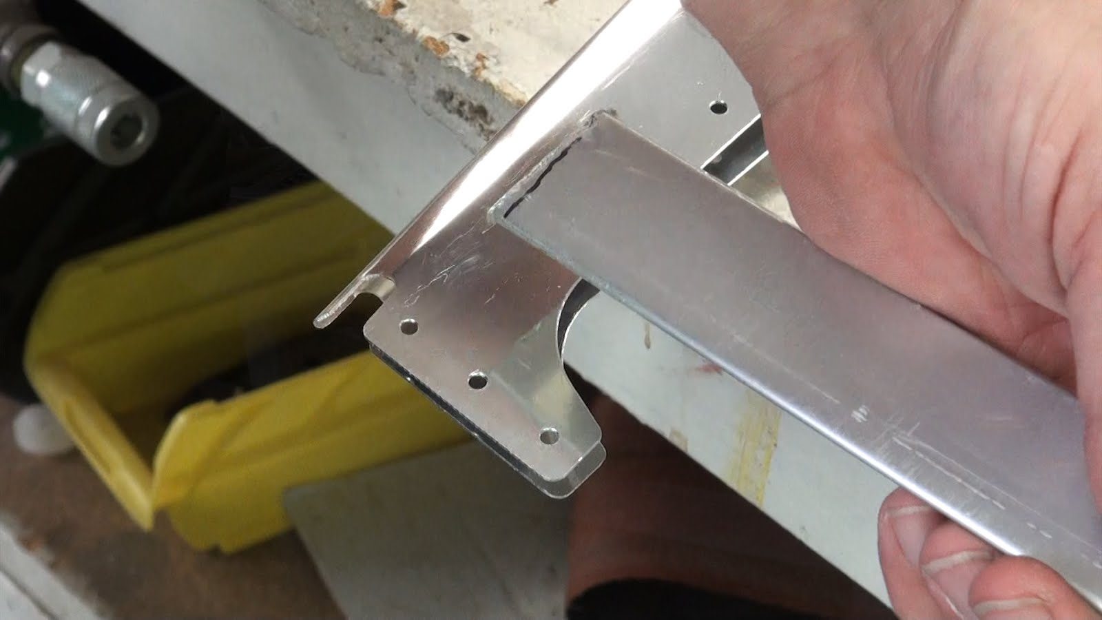
Next insert the trailing edge material in between each of the rib tabs. Position the trailing edge centered and parallel with the trailing edge tabs located on each rib.
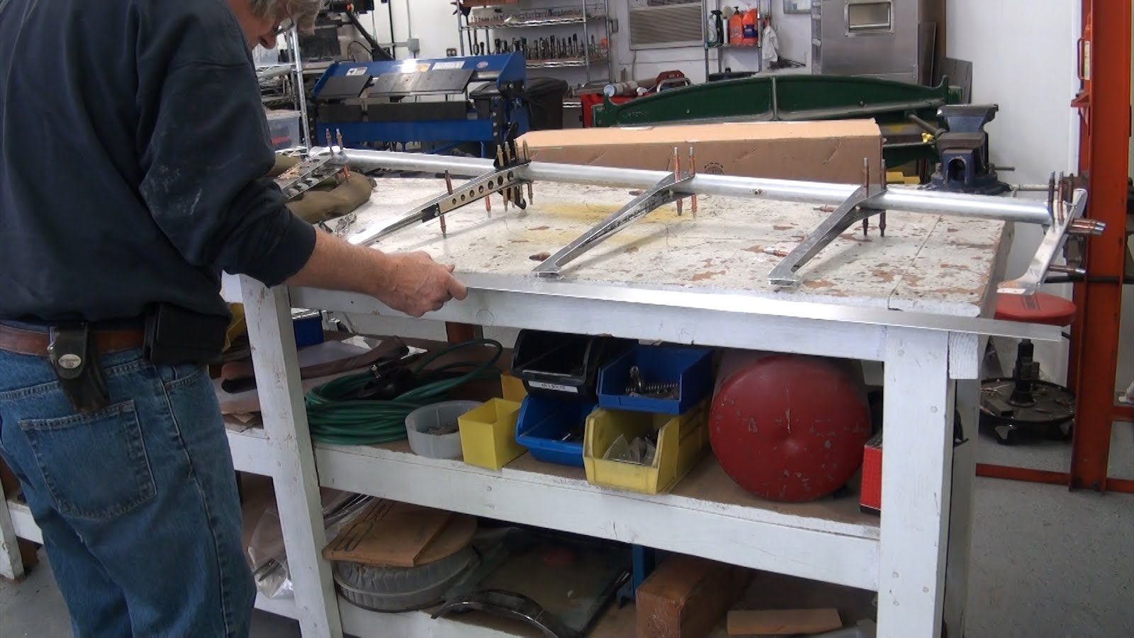
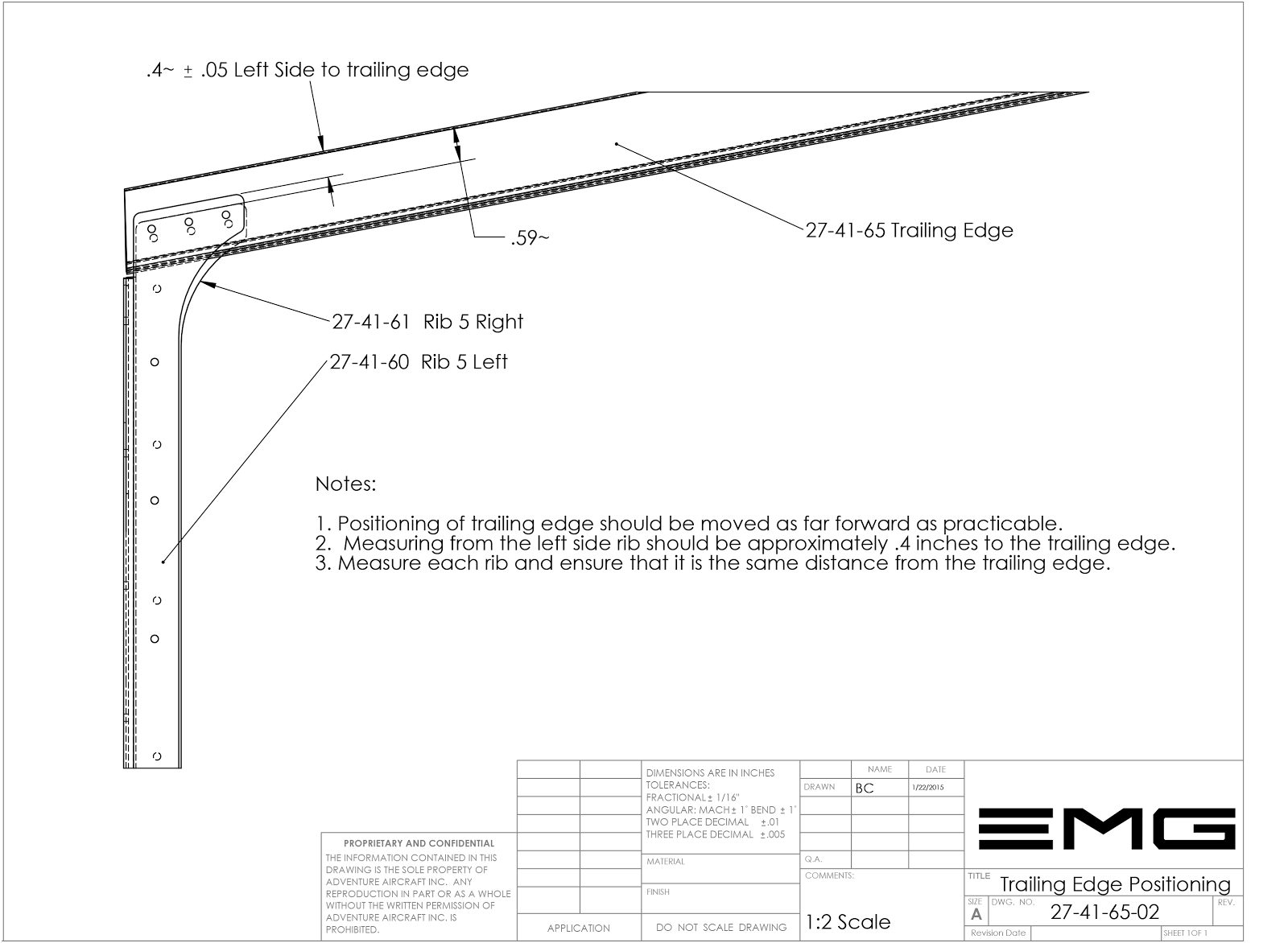
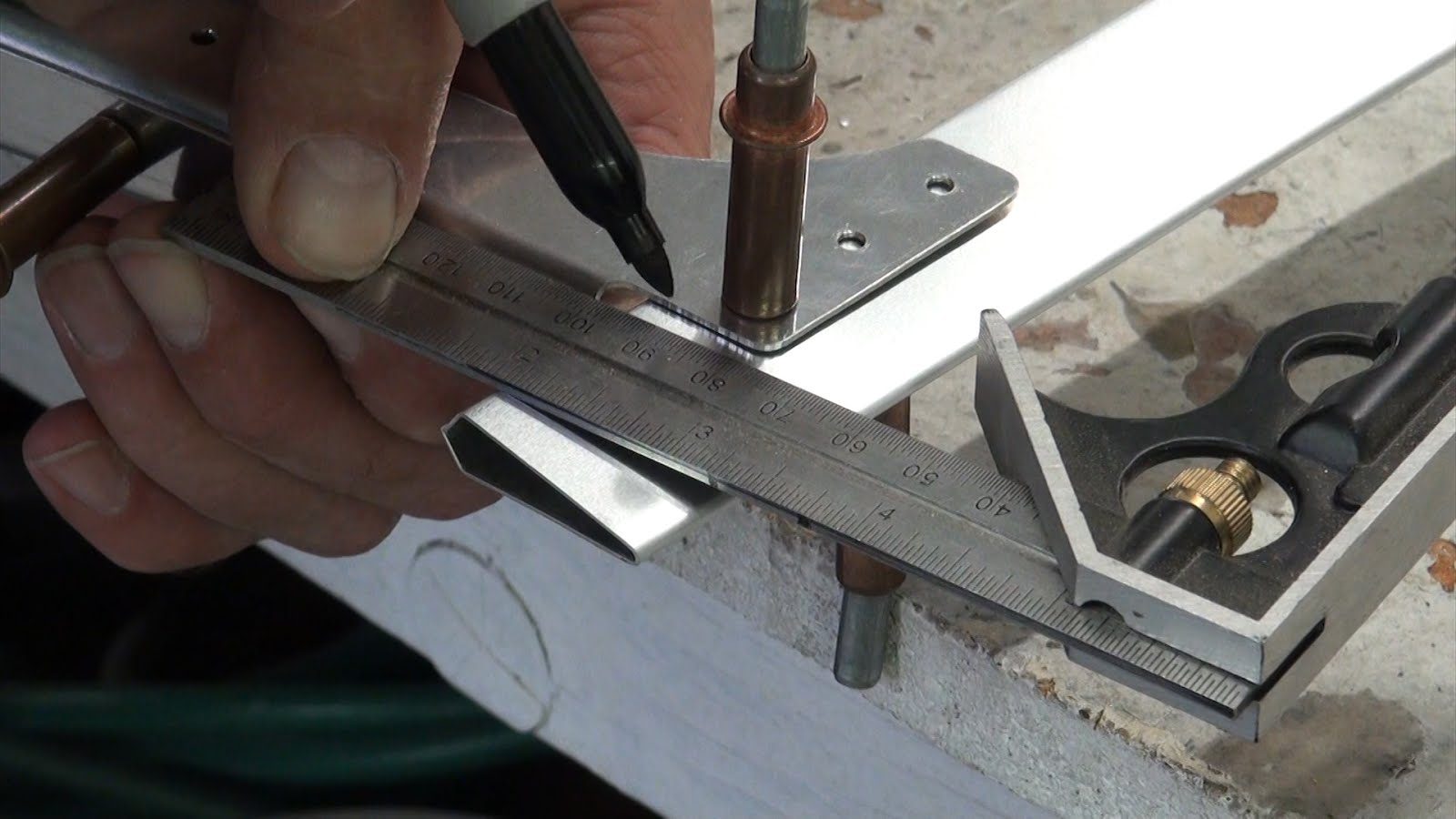
Using a pair of calipers or ruler measure the distance from the trailing edge to the edge of each rib.
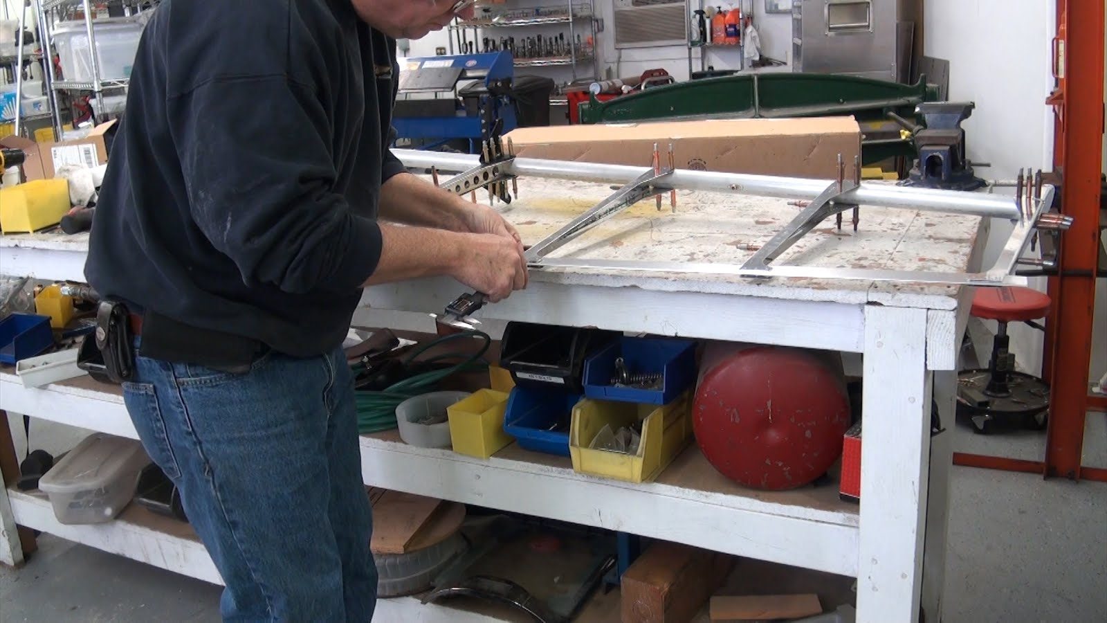
For proper positioning refer to drawing number 27-41-65-02 Trailing Edge Positioning. During the installation of the trailing edge you should be able to site down from both ends while you are drilling to ensure that the trailing edge positioning is centered on the profile of the rudder.
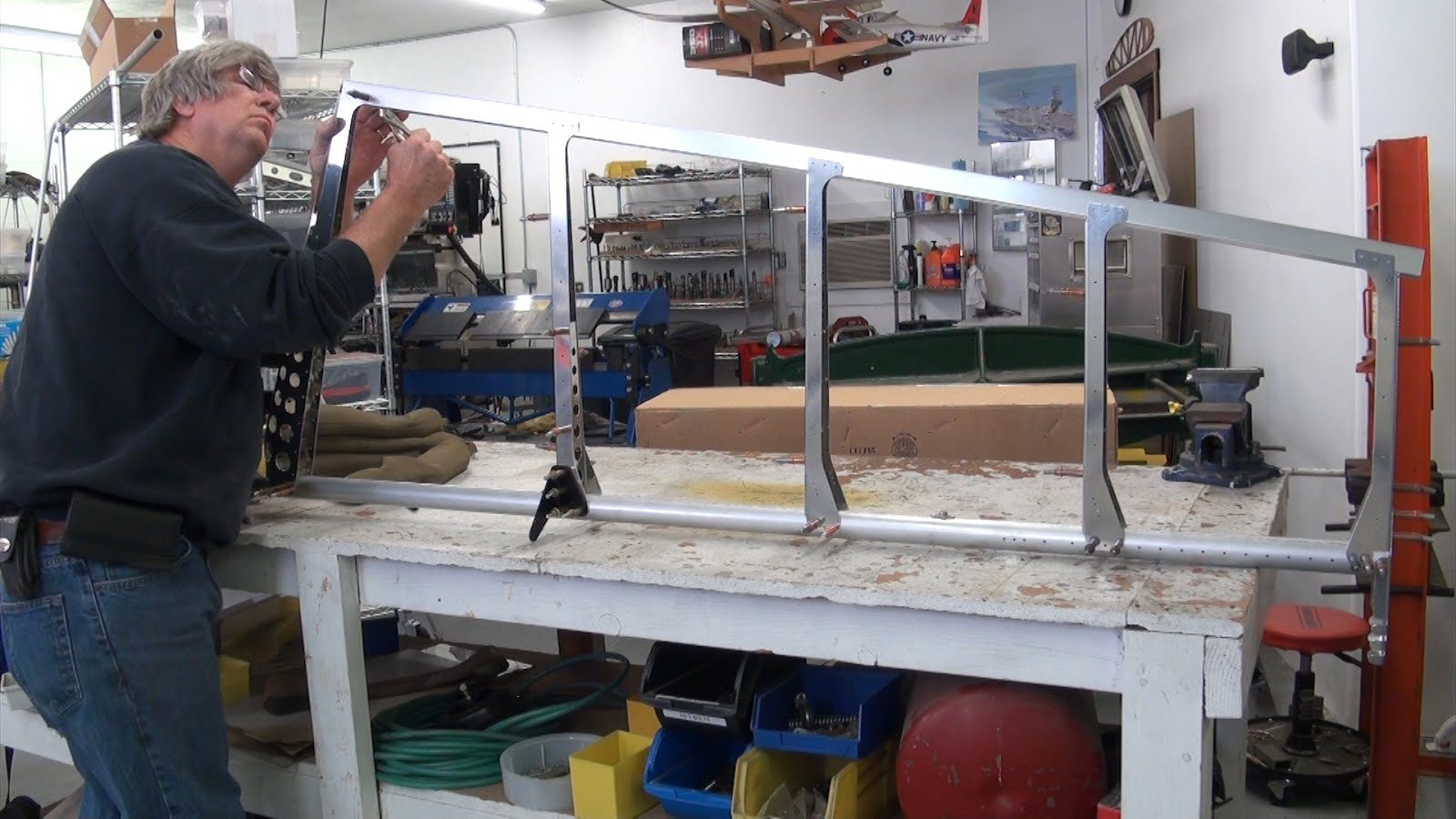
Drill only 1 hole in each side of rib #1 and rib #5 and verify that the trailing edge is perfectly centered then proceed to drill the remaining holes alternating from side to side and from rib to rib once again ensuring that the trailing edge remain centered and straight during the drilling and cleco in process.
27-41-65-02 Trailing Edge Positioning
Trim Trailing Edge at Rib #5
Once the trailing edge has been properly positioned and all of the holes drilled you will need to mark the trailing edge at the rib #5 position and cut it to match the profile of #5 rib.
Rib Number 7
Insert rib number 7 into the lower dge of the leading edge sheet-metal skin. Cleco in place every 3 to 4 rivet holes.
Leading Edge Installation
Revision 1 to the rudder assembly changes the leading edge to the new style wrap around “D” tube construction leading-edge.
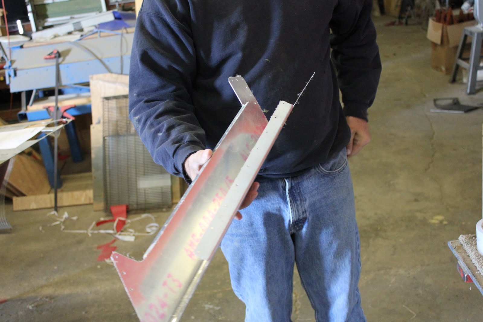
The leading-edge will be squeezed together and then riveted along the overlapping flanges that form the false spar. These can be riveted together with 1/8″ aluminum pop rivets.
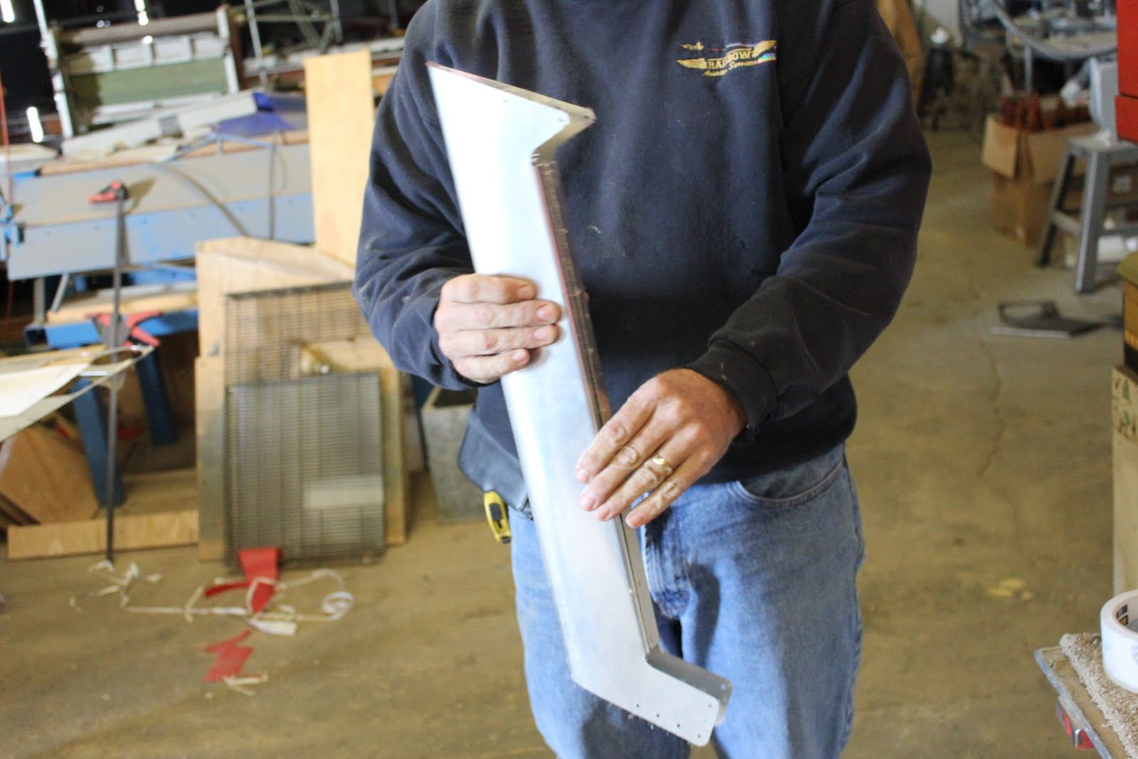
Next step is to Cleco the leading edge to rib #7 on the bottom and rib #6 on the top as well as the overlapping section on to the top of the main spar.l the leading edge
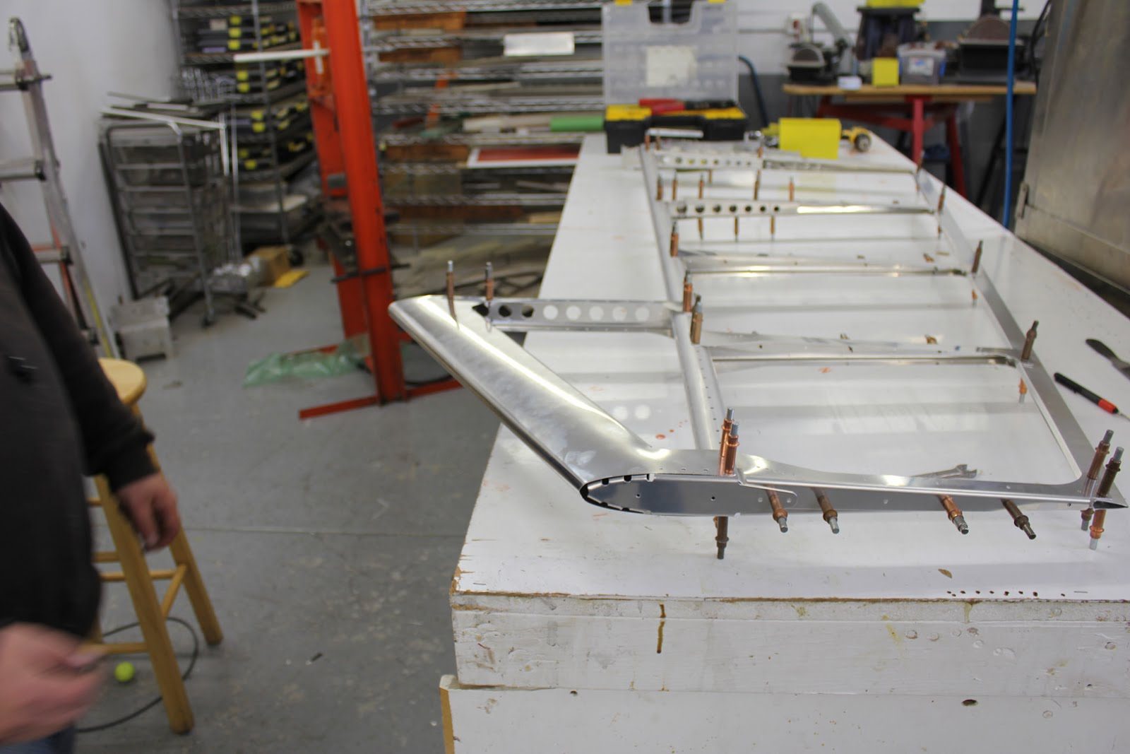
Riveting
Refer to drawing 27-41-00-09 for rivet placement.
Leading-Edge Riveting
We can begin by riveting the leading-edge to rib #7, and #6.
Trailing Edge Riveting
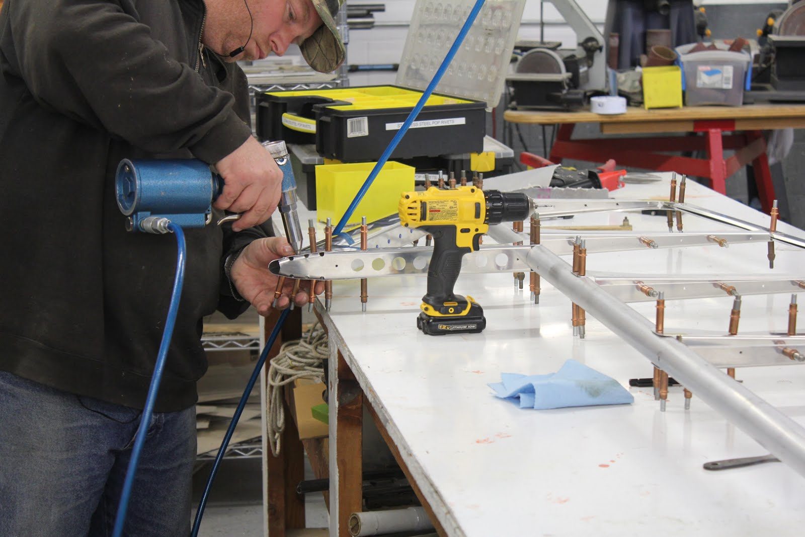
BSPS-4-2 aluminum pop rivets in the trailing edge. Removed 2 cleco’s from each rib and insert rivets, then go back and remove the remaining cleco’s and install rivets in those holes.
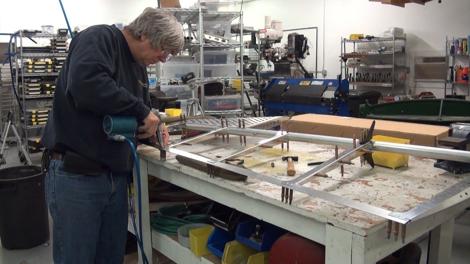
Join Ribs
CCP-4-2 stainless steel pop rivets for joining the rib halves.
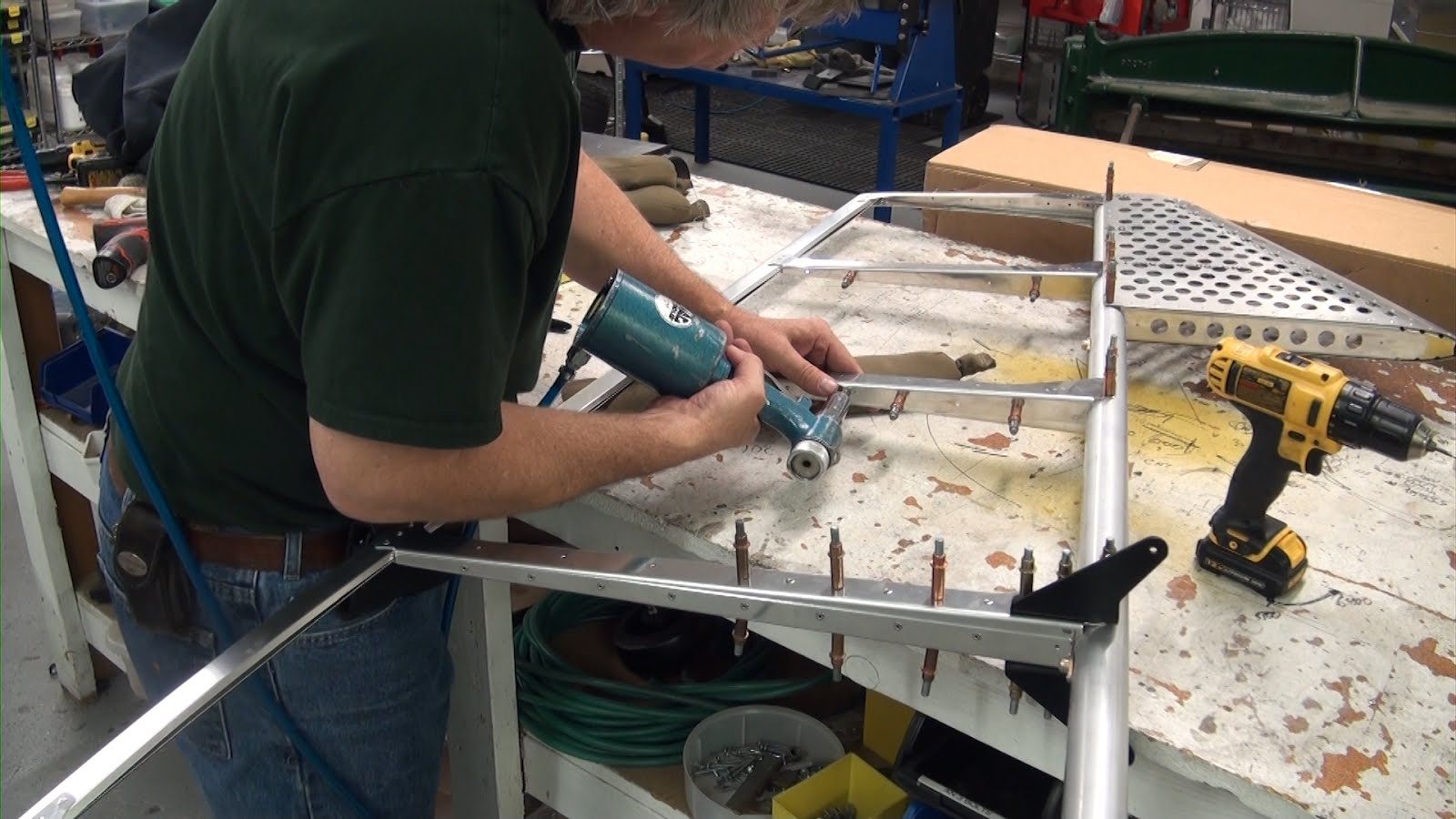
Attaching Ribs to Spar
CCP-4 – 4 stainless steel pop rivets are used for attaching all of the ribs to the rudder spar.
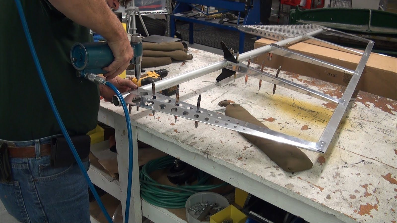
Rivet Layout Rib 1 and 2
All of the holes that are on the side of rib 3, 4, 5 are holes that are used to attach the fabric to the rudder structure and do not require any rivets until at the time of fabric installation.
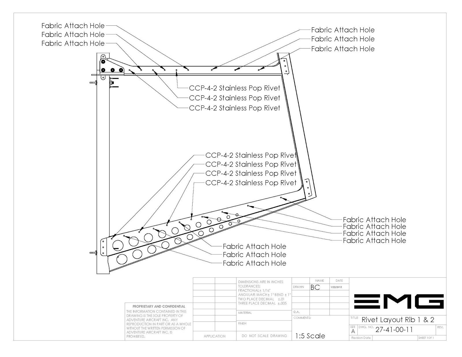
In ribs 1 and 2 there are rib support ribs that need to be secured with stainless steel pop rivets. We will be using CCP-4–2 stainless steel pop rivets in the specified locations. Refer to drawing 27-41-00-11 rivet layout rib 1 & 2. for the proper location of the stainless steel pop rivets.
Additional References
//www.electricmotorglider.com/2015/10/emg-6-shop-notes-november-2015.html